Ultrasonic sensor

a technology of ultrasonic sensor and conversion device, which is applied in the field of ultrasonic sensor, can solve the problem that the manufacturing process of the receiver is not necessary, and achieve the effect of reducing the influence of vibration reducing the acoustic crosstalk among the conversion device, and improving the accuracy of detecting physical quantities of a target object for detection

Inactive Publication Date: 2007-05-08
DENSO CORP
View PDF9 Cites 5 Cited by
  • Summary
  • Abstract
  • Description
  • Claims
  • Application Information

AI Technical Summary

Benefits of technology

[0012]It is therefore an object of the present invention to provide, with a low manufacturing cost, an ultrasonic sensor which:
[0013](1) is small and lightweight and reduces the crosstalk among the vibration plates to make it possible to determine with a high degree of accuracy the position and the distance of the target object; or
[0016]In the case that conversion devices convert the first ultrasonic signal to the electric signal after receiving the first ultrasonic signal, influences of vibrations among the conversion devices can be reduced, because the sizes of the conversion devices are uneven. Therefore an acoustic crosstalk among the conversion devices can be reduced. In addition, accuracy of detecting physical quantities of a target object for the detection can be improved.
[0017]In addition, since the effect described above can be achieved by simply making the sizes of the conversion devices uneven, an unordinary process is not necessary in manufacturing the receiver. Therefore, it is possible to reduce the manufacturing cost of the ultrasonic sensor compared to the ultrasonic sensor described in JP-H5-347797-A, which requires a process for injecting the filling materials.
[0018]In addition, since the intervals among the conversion devices can be reduced to be minimum for preventing the transmissions of the vibrations among them, the ultrasonic sensor can be designed to be smaller and more lightweight by an amount of the filling materials required for the ultrasonic sensor described in JP-H5-347797-A.

Problems solved by technology

In addition, since the effect described above can be achieved by simply making the sizes of the conversion devices uneven, an unordinary process is not necessary in manufacturing the receiver.

Method used


Image

  • Ultrasonic sensor
  • Ultrasonic sensor
  • Ultrasonic sensor

Examples


first embodiment

[Effect and Advantage of First Embodiment]

[0058]Hereafter effects and advantages of the ultrasonic sensor according to the first embodiment will be described.

[1-1]

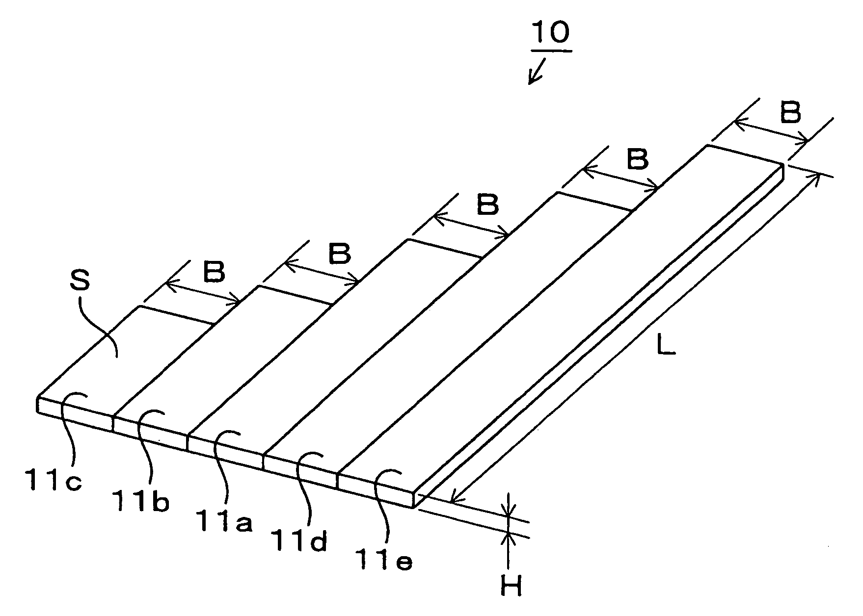
[0059]A transmitter (not shown) of the ultrasonic sensor which is constructed separately of the receiver 10 transmits an ultrasonic signal to a target object for detection, and the reception elements 11a–11e of the receiver 10 receive the ultrasonic signal reflected by the target object.

[0060]The receiver 10 detects gaps among timings at each of which one of the reception elements 11a–11e receives the reflected ultrasonic signal. Then the receiver 10 determines the two-dimensional or three-dimensional position of the target object and a distance to the target object by comparing the detected gaps with the ultrasonic signal transmitted by the transmitter. The transmitter may be of any type, including the piezoelectric type and the capacitance type.

[1-2]

[0061]As shown in FIG. 5, the vibration plate fixed at its both ends has...

second embodiment

(Second Embodiment)

[0090]An ultrasonic sensor of a second embodiment is different from that of the first embodiment in that the ultrasonic sensor of the second embodiment has the receiver 50 shown in FIG. 8 in place of the receiver 10. As shown in FIG. 8, the receiver 50 includes five reception elements (i.e. conversion devices) 51a–51e, each of which has a shape of a flat rectangular plate.

[0091]The reception elements 51a–51e are arranged one-dimensionally on a plane with their reception surfaces S having the same surface level. Specifically, the reception surfaces S face the same direction and the reception elements 51a–51e are aligned with small intervals in the width direction thereof. In the alignment, each of a first longitudinal ends and a second longitudinal ends of the reception elements 51a–51e is aligned in a straight line, where the first longitudinal ends consist of longitudinal ends of the reception elements 51a–51e at a certain side of the reception elements 51a–51e, ...

third embodiment

(Third Embodiment)

[0119]An ultrasonic sensor of a third embodiment is different from that of the first embodiment in that the ultrasonic sensor of the third embodiment has the receiver 60 shown in FIG. 10 in place of the receiver 10. As shown in FIG. 10, the receiver 60 includes five reception elements (i.e. conversion devices) 61a–61e, each of which has a shape of a flat rectangular plate.

[0120]The reception elements 61a–61e are arranged one-dimensionally on a plane with their reception surfaces S having the same surface level. Specifically, the reception surfaces S face the same direction and the reception elements 61a–61e are aligned with small intervals in the width direction thereof. In the alignment, each of a first longitudinal ends and a second longitudinal ends of the reception elements 61a–61e is aligned in a straight line, where the first longitudinal ends consist of longitudinal ends of the reception elements 61a–61e at a certain side of the reception elements 61a–61e, a...


PUM


Abstract

A receiver of an ultrasonic sensor includes reception elements, each of which has a shape of a flat rectangular plate. The reception elements are arranged one-dimensionally on a plane so that the reception surfaces face the same direction and that the reception elements are aligned with small intervals in the width direction thereof while longitudinal ends of the reception elements at a certain side are aligned in a straight line. The widths and the thicknesses of the reception elements are even, while the longitudes of the reception elements are uneven. The both longitudinal ends of the reception elements are fixed to prohibit the vibration of the ends. The longitudes are designed so that the primary resonance frequencies of the reception elements are uneven.

Description

CROSS REFERENCE TO RELATED APPLICATION[0001]This application is based on and incorporates herein by reference Japanese patent application No. 2005-11484 filed on Jan. 19, 2005.FIELD OF THE INVENTION[0002]The present invention relates to an ultrasonic sensor and in particular to an ultrasonic sensor which converts a received ultrasonic signal to an electric signal or transmits an ultrasonic signal by converting an electric signal to the ultrasonic signal.BACKGROUND OF THE INVENTION[0003]Conventionally, an ultrasonic sensor is widely used in various fields. For example, it is used as a vertical sonar in an echo sounding machine and a fish detector, as a horizontal sonar for a vessel detecting a direction or a distance to an object, and as an ultrasonic diagnostic equipment for making a diagnosis of an internal organ by imaging the organ.[0004]In addition, developments have been made for using the ultrasonic sensor in an art for monitoring a vehicle periphery and thus contributing to d...

Claims


Application Information

Patent Timeline
Patent Type & Authority Patents(United States)
IPC IPC(8): G01H11/00H01L41/08
CPCG01H3/08G01S7/521
Inventor ITOH, TOMOKISUGIURA, MAKIKO
Owner DENSO CORP
Why Eureka
Try Eureka