Ink Jet Process

a technology of ink jet and process, applied in the field of ink jet process, can solve the problems of affecting the shape and size of the paste, increasing the chance of damaging the transparent substrate and the fabricated patterns, and increasing the material usage of the conventional coating of red, green and blue color photoresist, so as to reduce the problem of overflow of the paste, reducing the problem of plugged print heads, and reducing the effect of paste size and shap

Inactive Publication Date: 2007-05-31
CHUNGHWA PICTURE TUBES LTD
View PDF5 Cites 4 Cited by
  • Summary
  • Abstract
  • Description
  • Claims
  • Application Information

AI Technical Summary

Benefits of technology

[0012] In contrast to the conventional ink jet process, the claimed invention utilizes the combination of a heating light source and an optical system to partially heat the paste just sprayed on a glass substrate thereby controlling the heating area and heating time of the paste. Additionally, the heating light source of the claimed invention is able to move in synchrony with the print head, thereby maintaining the shape and size of the paste and reducing problems such as plugged print heads, overflow of the paste, and uneven paste size and shape as caused by the conventional ink jet process.

Problems solved by technology

However, in addition to performing numerous photolithography and cleaning processes, the total material usage of the conventional coating of the red, green, and blue color photoresist is only 1-2%.
Additionally, numerous depositions, photolithography, etching, and cleaning processes must be performed on the TFT array substrate for fabricating pixel electrodes, scan lines, and data lines, thereby increasing the chance of damaging the transparent substrate and the fabricated patterns should the substrate and patterns come in contact with any of the numerous chemical agents utilized.
If a large area device, such as a hot plate were utilized to directly bake the glass substrate 26, the high temperature produced by the hot plate would cause two unwanted results.
Second, this method will cause uneven baking time for each pattern formed on the glass substrate 26.
Furthermore, the two step approach of the conventional inkjet process increases the total time required by the fabrication process.
Because the two step approach of the conventional ink jet process often cannot control the size of the paste sprayed over the surface of the glass substrate, Japanese Patent No.
Nevertheless, this method will not only increase the number of fabrication steps and the overall cost of manufacturing, but also reduce the light penetration of the liquid crystal display.
Moreover, the proposed method is unable to be applied to other materials that can be sprayed via the ink jet process, including polyimide, silver paste, and liquid crystals.

Method used


Image

  • Ink Jet Process
  • Ink Jet Process
  • Ink Jet Process

Examples


Embodiment Construction

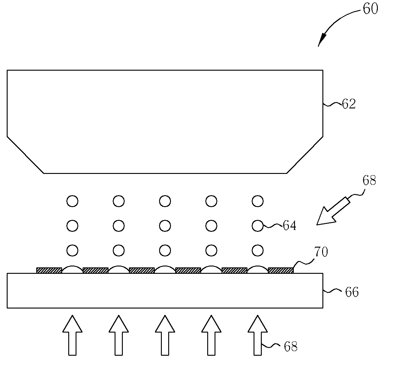
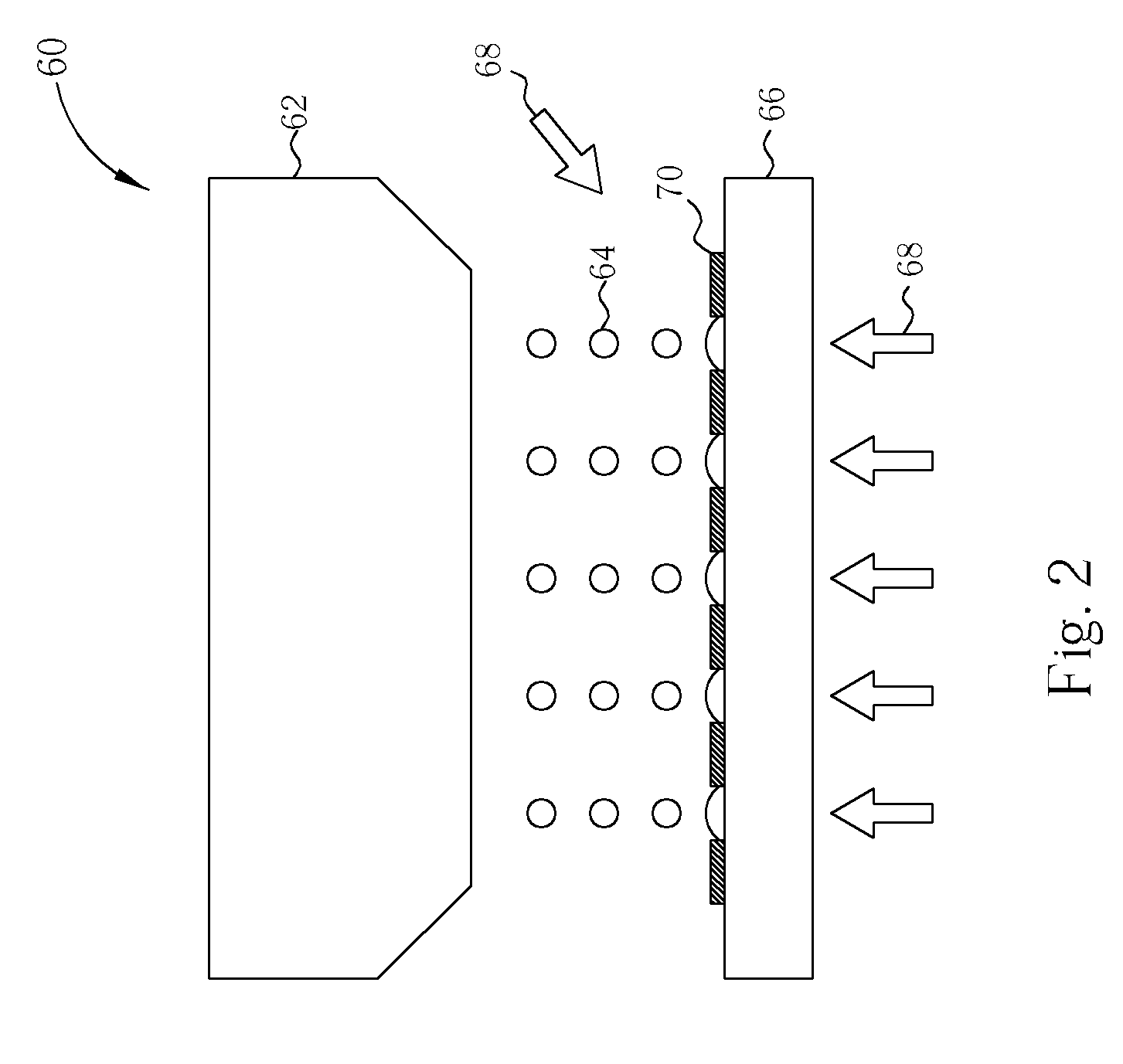
[0017] Please refer to FIG. 2. FIG. 2 is a perspective diagram showing the ink jet process according to the present invention. As shown in FIG. 2, a glass substrate 66, such as a color filter substrate, is provided, and an ink jet equipment 60 is utilized to fabricate the required color filter pattern on the glass substrate 66. Preferably, the ink jet equipment 60 includes at least a print head 62 and a controller (not shown) that functions to provide paste to the print head 62 and also to control the movement of the print head 62. Additionally, the surface of the glass substrate 66 includes a black matrix 70 for increasing the contrast of the liquid crystal display and shielding the non-transparent portion of the thin film transistors on the TFT array substrate, scan lines, and data lines. Subsequently, a colored photoresist paste 64 is sprayed onto the surface of the glass substrate 66 by utilizing the print head 62 according to various fabrication processes and product requiremen...


PUM


Abstract

An ink jet process includes: providing a substrate; performing a ink jet step for spraying a paste on the surface of the substrate; and performing an in-situ and partial heating process to directly heat the paste sprayed on the surface of the substrate and control the shape and location of the paste.

Description

BACKGROUND OF THE INVENTION [0001] 1. Field of the Invention [0002] The invention relates to an ink jet process, and more particularly, to an ink jet process utilizing a heating light source. [0003] 2. Description of the Prior Art [0004] The advantages of the liquid crystal displays (LCDs) include lighter weight, less electrical consumption, and less radiation contamination than their CRT counterparts. Thus, the LCDs have been widely applied to several portable information products, such as: notebook computers, PDAs, etc. Additionally, the LCDs are gradually replacing the CRT monitors of the conventional desktop computers. The incident light will produce different polarization or refraction when the alignments of these liquid crystal molecules are different. The LCDs utilize the characteristics of the liquid crystal molecules to control the light transmittance and produce gorgeous images. [0005] In general, liquid crystal displays include a thin film transistor (TFT) array substrate...

Claims


Application Information

Patent Timeline
Patent Type & Authority Applications(United States)
IPC IPC(8): B41J2/01
CPCB41J11/002G02B5/201G02F1/133516B41J11/00216B41J11/00214
Inventor WU, CHUAN-YILIN, YI-PEN
Owner CHUNGHWA PICTURE TUBES LTD
Why Eureka
Try Eureka