
Magnetic gear-based power-coupled composite motor and a control method thereof

A technology of magnetic gears and composite motors, which is applied in the direction of motors, drive control, and mechanical energy control. It can solve problems such as power waste, and achieve the effects of reducing costs, requiring no lubrication and maintenance, and reducing power levels.

Active Publication Date: 2019-09-27
JIANGSU UNIV
View PDF4 Cites 7 Cited by
  • Summary
  • Abstract
  • Description
  • Claims
  • Application Information

AI Technical Summary

Problems solved by technology

[0004] In the research of electric tractors, especially electric tractors driven by dual motors, the drive mode in which two motors work independently is usually used at present, that is, one motor alone drives the output shaft of the power take-off (PTO), and the other motor It is responsible for driving the wheels, which is the so-called dual-motor independent drive method. This method has the advantages of simple structure, but there are also many problems. For example, when the electric tractor does not need the PTO output shaft to output power, only one drive motor in the system works. And the other motor does not work all the time, causing serious power waste

Method used


Image

  • Magnetic gear-based power-coupled composite motor and a control method thereof
  • Magnetic gear-based power-coupled composite motor and a control method thereof
  • Magnetic gear-based power-coupled composite motor and a control method thereof

Examples


Embodiment Construction

[0024] The scheme of the present invention will be described in further detail below in conjunction with the accompanying drawings.

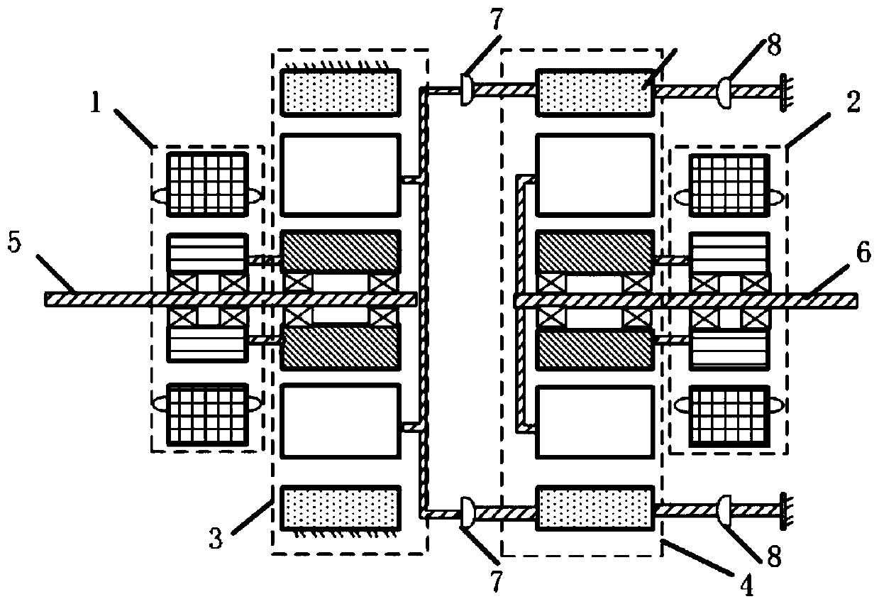
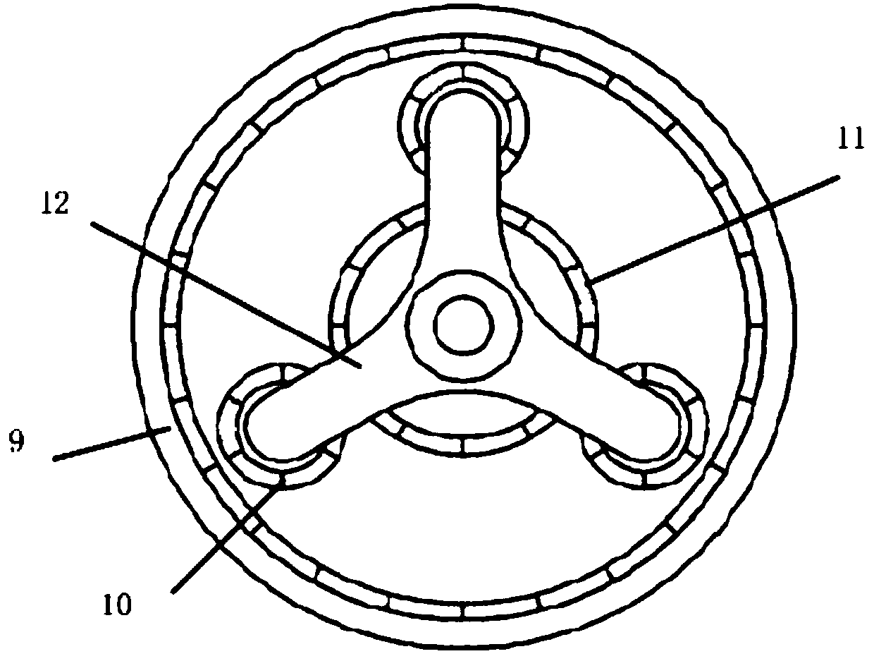
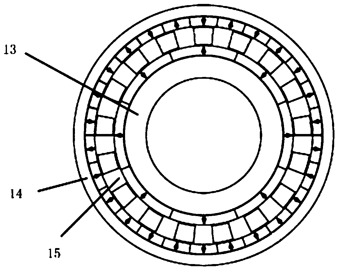
[0025] like figure 1 As shown, the magnetic gear power coupling (MG-PC) composite motor structure of the present invention includes a permanent magnet vernier motor I1, a high power density built-in permanent magnet motor II2, a magnetic gear I3, a magnetic gear II4, and a PTO output shaft 5 , traction output shaft 6, clutch I7, clutch II8, stator of motor I1, rotor of motor I1, stator of motor II2, rotor of motor II2, inner rotor of magnetic gear I3, intermediate rotor of magnetic gear I3, of magnetic gear I3 Outer rotor, inner rotor of magnetic gear II4, intermediate rotor of magnetic gear II4, outer rotor of magnetic gear II4.

[0026] The motor I1 and the magnetic gear I3 are connected and arranged through the PTO output shaft 5, the rotor of the motor I1 is mechanically connected with the inner rotor of the magnetic gear I3, the motor II2 ...


PUM


Abstract

The invention discloses a magnetic gear-based power-coupled composite motor and a control method thereof. The composite motor successively comprises, from a side to the other side, a motor I, a magnetic gear I, a magnetic gear II and a motor II, wherein the output shaft of the motor I is connected to the inner rotor of the magnetic gear I; the output shaft of the motor II is connected to the inner rotor of the magnetic gear II; the outer rotor of the magnetic gear I is locked; the intermediate rotor of the magnetic gear I, while being connected to a PTO output shaft, is connected to the outer rotor of the magnetic gear II through a clutch I; the outer rotor of the magnetic gear II can be locked by a clutch II; and the intermediate rotor of the magnetic gear II is connected to a traction output shaft. The dual motors of the present invention can be coupled to each other to realize operation assistance, and can also perform respective operation separately. The composite motor overcomes a defect that each motor in a conventional dual-motor driving system can only perform its own driving task and enhances the system reliability.

Description

technical field [0001] The invention relates to a magnetic gear-based power coupling compound motor, which belongs to the technical field of high-end agricultural equipment manufacturing, and is especially proposed for an electric tractor and a magnetic gear power coupling compound motor used in a dual-motor drive system and a control method. Background technique [0002] Increasingly severe energy and environmental issues have prompted the development of transportation and agricultural equipment in an efficient, clean and sustainable direction. From the perspective of the development direction of new energy and the application of new technologies, agricultural equipment will gradually become electrified. Replacing traditional internal combustion tractors with electric tractors is one of the first choices to meet the requirements of environmentally friendly high-end agricultural equipment operations. [0003] On the other hand, the traditional transmission equipment system u...

Claims


Application Information

Patent Timeline
Patent Type & Authority Applications(China)
IPC IPC(8): H02K7/116H02K49/10B60L15/20
CPCH02K7/116H02K49/106B60L15/20B60L2220/42Y02T10/64Y02T10/72
Inventor 全力张凯杜怿朱孝勇浦尉玲
Owner JIANGSU UNIV
Learn More