
A data center network routing and switching system and method based on flow characteristics

A data center network and switching system technology, applied in the data center network routing switching system based on flow characteristics, network traffic routing field, can solve problems such as throughput decline, unbalanced traffic, network congestion, etc.

Active Publication Date: 2020-10-27
河南信大网御科技有限公司 +1
View PDF7 Cites 0 Cited by
  • Summary
  • Abstract
  • Description
  • Claims
  • Application Information

AI Technical Summary

Problems solved by technology

However, studies have shown that the length of traffic in the data center network is significantly unbalanced: 90% of the flow length does not exceed 1M, while a small number of flows with a length of more than 100M occupy most of the bandwidth in the network; resulting in data network The center has the problem of low efficiency of multi-path traffic transmission
[0004] The shortest path first routing method is suitable for flows with a small length, but it may map multiple flows with a long length to the same link, causing network congestion and packet loss, resulting in a decrease in throughput

Method used


Image

  • A data center network routing and switching system and method based on flow characteristics
  • A data center network routing and switching system and method based on flow characteristics
  • A data center network routing and switching system and method based on flow characteristics

Examples


Embodiment 1

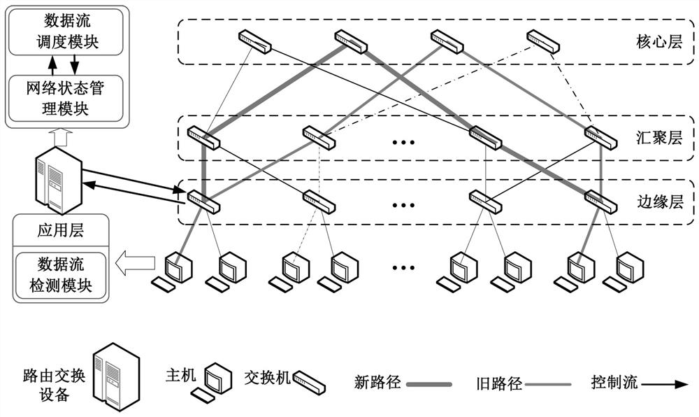
[0047] as attached figure 1As shown, a data center network routing and switching system based on flow characteristics, which includes a data flow detection module, a network status management module and a data flow scheduling module; the data flow detection module collects the data flow received by the data center network in real time TCP cache value, the data flow is screened for the first time according to the detected TCP cache value, and the first screening result is transmitted to the data flow scheduling module; when performing the first screening, if the data flow If the TCP cache value does not exceed the preset threshold, it is determined that the data flow is the first data flow, otherwise it is determined that the data flow is the second data flow; the data flow scheduling module receives the first screening result and the current network State information, using a data stream selection algorithm to perform a second screening on the second data stream, and divide th...

Embodiment 2

[0063] In the step 2, a method of marking the filtered second data flow is also included: when the TCP cache value of the detected data flow exceeds a preset threshold, the data flow detection module modifies the data flow The IP service type in the packet header marks the data flow. Preferably, the first 6 bits of the IP service type in the header of the data packet of the second data flow are set to 000011XX.

[0064] The marking method is as follows: the detection logic of the data flow detection module is realized based on the kernel module of the operating system, and the data flow detection module detects the TCP cache value in real time, and when it is found that the cache exceeds a preset threshold, by setting The differentiated service domain (Differentiated Service Code Point, DSCP) marks the data flow, and the DSCP domain is the first 6 bits of the service type (Type of Service, TOS) field in the data packet header, such as figure 2 As shown, 000011XX indicates th...

Embodiment 3

[0067] In the step 3, when the data flow selection algorithm is used to perform the second screening on the second data flow, with the goal of ensuring the maximum current network throughput, the screening is performed from the marked large flows, and the specific steps are:

[0068] Set m links in the network l 1 , l 2 ,..., l m , each link has two attributes, the available bandwidth of the link B j , and the set F of the second data streams passing through the link j , j=1, 2, ..., m;

[0069] Step 3.1, determine the objective function

[0070] The objective function F is set as the throughput of the second data flow set passing on each link in the data center network, and the calculation formula of the objective function F is:

[0071]

[0072] When filtering, it is guaranteed that the total throughput of the data flow set passing through each link does not exceed the available bandwidth of the link. Therefore, the constraints of the objective function F are:

[00...


PUM


Abstract

The present invention provides a data center network routing switching system and method based on flow characteristics. The system includes a data flow detection module, a network state management module and a data flow scheduling module; Screen once, and transmit the result of the first screening to the data flow scheduling module; the network state management module detects the current network state information of the data center network in real time; the data flow scheduling module performs the second data flow on the second data flow secondary screening, dividing it into data flow I and data flow II, and dynamically adjusting the transmission path of data flow II according to the current network state information; the network state management module receives the dynamic adjustment result and forwards it to the switch at the edge layer, The switch at the edge layer controls the forwarding of the data flow II according to the dynamic adjustment result. The invention improves the flow transmission rate and network throughput in the data center network.

Description

technical field [0001] The invention relates to the field of computer networks and network traffic routing, in particular to a data center network routing and switching system and method based on flow characteristics. Background technique [0002] With the exponential growth of Internet applications and services, data centers have gradually become an irreplaceable information service infrastructure. The deployment of a large number of bandwidth-intensive services leads to an increase in the internal traffic of the data center, and the traditional hierarchical tree-based network architecture has problems such as limited bandwidth and poor scalability. Therefore, many new topologies (Fat-Tree, VL2, DCell) It is proposed that these architectures provide multi-path transmission methods to obtain higher bisection bandwidth and reliability. [0003] The current multi-path routing algorithms widely used in data center networks, such as equal-cost multi-path routing and Valiant Loa...

Claims


Application Information

Patent Timeline
Patent Type & Authority Patents(China)
IPC IPC(8): H04L12/707H04L12/721H04L12/801H04L45/24
CPCH04L47/12H04L47/29H04L45/38H04L45/123H04L45/24
Inventor 郭义伟冯志峰孙统帅鲍尚策张建军宋延坡李浩
Owner 河南信大网御科技有限公司
Learn More