
Ankle joint power-assisted exoskeleton

A technology of exoskeleton and ankle joints, which is applied in the direction of appliances that help people walk, belts/chains/gears, physical therapy, etc. It can solve the problems of reduced power-assist effect, large volume, mass, and weight, and achieve the reduction of the quality of subsidiary mechanisms , Small size, light weight effect

Pending Publication Date: 2019-10-01
SOUTH UNIVERSITY OF SCIENCE AND TECHNOLOGY OF CHINA
View PDF0 Cites 12 Cited by
  • Summary
  • Abstract
  • Description
  • Claims
  • Application Information

AI Technical Summary

Problems solved by technology

However, since there is no injection of external energy, the assistance provided is always limited and cannot be further improved.
[0004] Active rigid exoskeletons generally use direct assist, which can provide high enough assist power, so they require high motor power. Generally, they are heavy, poor in ergonomics, low in portability and comfort, and most of them are difficult to reduce walking. energy consumption
The active flexible exoskeleton can reduce the mass and improve the human-machine coordination. However, the deformation of the flexible material during walking reduces the power-assisted effect, and because the human skin cannot bear excessive pressure for a long time, the tightness of the bandage To control within the appropriate range, reduce the slippage of the flexible exoskeleton during the movement of the human body
[0005] Among the existing wearable exoskeleton robots, most of the active rigid exoskeleton robots use high-power motors to directly assist, that is, to assist the ankle joints during the pedaling stage. Due to the large volume and mass of high-power motors and their auxiliary structures , so the wearing convenience is low, resulting in low coordination between exoskeleton joint motion and human joint motion, making it difficult to apply to various complex environments common in daily life; and because of the use of high-power motors, if an accident occurs during wearing Can cause serious damage to the human body

Method used


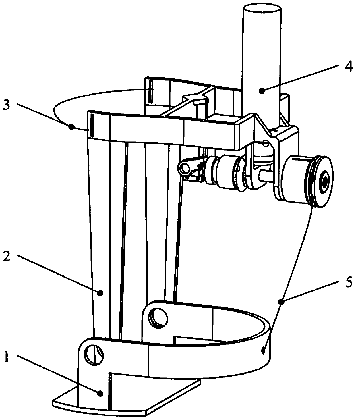
Image

  • Ankle joint power-assisted exoskeleton
  • Ankle joint power-assisted exoskeleton

Examples


Embodiment Construction

[0019] The object of the present invention is to propose a light-duty ankle exoskeleton booster mechanism with peak power amplification. The ankle exoskeleton booster mechanism considers that the direct booster exoskeleton only provides boosting when the pedal is on the ground in a gait cycle. It is characterized by short time and high power. The work time is only about 18% of the entire gait cycle, and the output power of the motor cannot be used well. However, if the motor is stored in the remaining 82% of the gait cycle with the help of springs and other energy storage mechanisms The work done is concentrated and released when assistance is needed, which can greatly reduce the requirements for motor power.

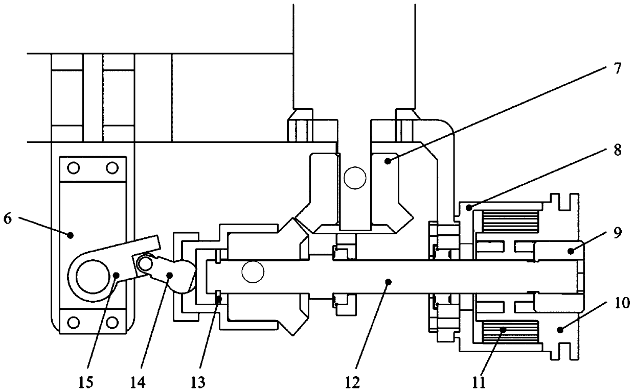
[0020] The invention discloses an ankle joint power-assisted exoskeleton, comprising a power mechanism, a clutch, an exoskeleton frame pedal 1, and an exoskeleton frame 2, the power mechanism and the clutch are installed on the exoskeleton frame 2, the The exoskeleton f...


PUM


Abstract

The invention provides an ankle joint power-assisted exoskeleton. The ankle joint power-assisted exoskeleton comprises a power mechanism, a clutch, an exoskeleton frame pedal and an exoskeleton frame,the power mechanism and the clutch are mounted on the exoskeleton frame, and the exoskeleton frame pedal is movably connected with the exoskeleton frame; the power mechanism comprises a first drivingmechanism, a gear set, a transmission shaft, a coil spring, a coil spring inner ring, a coil spring outer ring and a rope. The gear set comprises a driving gear and a driven gear, an output shaft ofthe first driving mechanism drives the driving gear to rotate, the driven gear can drive the transmission shaft to rotate, and the transmission shaft is connected with the coil spring inner ring. Theankle joint power-assisted exoskeleton has the advantages that in combination with the characteristic that the ankle joint power-assisted exoskeleton has a short machine assistance stage and high power, a peak value power amplification mechanism is adopted, and in a non-power-assisted stage, the coil spring of an energy storage element is utilized to store power output by a low-power reduction motor and intensively releases the power in a power-assisted stage so that a low-power motor with light weight and small size can be selected, wherein the mass of an accessory mechanism of the low-powermotor is also reduced.

Description

technical field [0001] The invention relates to the field of electromechanical technology, in particular to an ankle joint power-assisted exoskeleton. Background technique [0002] With the development of society and the advancement of science and technology, human beings began to pursue the use of external equipment to assist the heavy and complicated work that human beings encounter in daily life. As a wearable device for the human body, the exoskeleton is a new type of robot that integrates gait analysis, mechatronics, biomechanics and many other fields. It can be widely used in military, medical and elderly assistance fields. In the military field, it can improve the combat capability of individual soldiers, enhance the load-bearing capacity, and increase the walking distance; in the medical field, it can help patients with gait rehabilitation and assist the disabled to walk; in the field of helping the elderly, it can assist people with limb movement disorders due to ol...

Claims


Application Information

Patent Timeline
IPC IPC(8): A61H3/00F16H33/02
CPCA61H3/00F16H33/02A61H2003/007A61H2201/165A61H2201/1659
Inventor 付成龙李泱冷雨泉钱岳鹏卢泽宇
Owner SOUTH UNIVERSITY OF SCIENCE AND TECHNOLOGY OF CHINA
Learn More