
Scrap discharging elbow with scrap guiding, filtering and self-cleaning functions

A self-cleaning and elbow technology, which is applied in the manufacture of tools, metal processing machinery parts, maintenance and safety accessories, etc., can solve the problems of dirty liquid, easy blockage of the mesh, and influence on the discharge of cutting fluid, etc., so as to improve the filtration accuracy , Improve the operating environment and prolong the effect of cleaning cycle

Inactive Publication Date: 2019-10-01
西安精雕软件科技有限公司
View PDF6 Cites 0 Cited by
  • Summary
  • Abstract
  • Description
  • Claims
  • Application Information

AI Technical Summary

Problems solved by technology

[0003] The traditional chip removal elbow uses the bottom mesh to discharge liquid, which will cause chips to leak from the mesh. After a long time of operation, the mesh will be easily blocked and affect the discharge of cutting fluid.
Moreover, there is no chip guide device inside the traditional chip removal elbow, chips will be easily stuck, and chip removal is difficult
In addition, there is no filtering structure inside the traditional chip removal elbow, and the cutting fluid will take a large amount of chips out
In summary, the traditional chip removal elbow has structural defects, resulting in unsmooth chip removal and unclean liquid discharge

Method used


Image

  • Scrap discharging elbow with scrap guiding, filtering and self-cleaning functions
  • Scrap discharging elbow with scrap guiding, filtering and self-cleaning functions
  • Scrap discharging elbow with scrap guiding, filtering and self-cleaning functions

Examples


Embodiment Construction

[0018] The present invention will be described in further detail below in conjunction with the accompanying drawings.

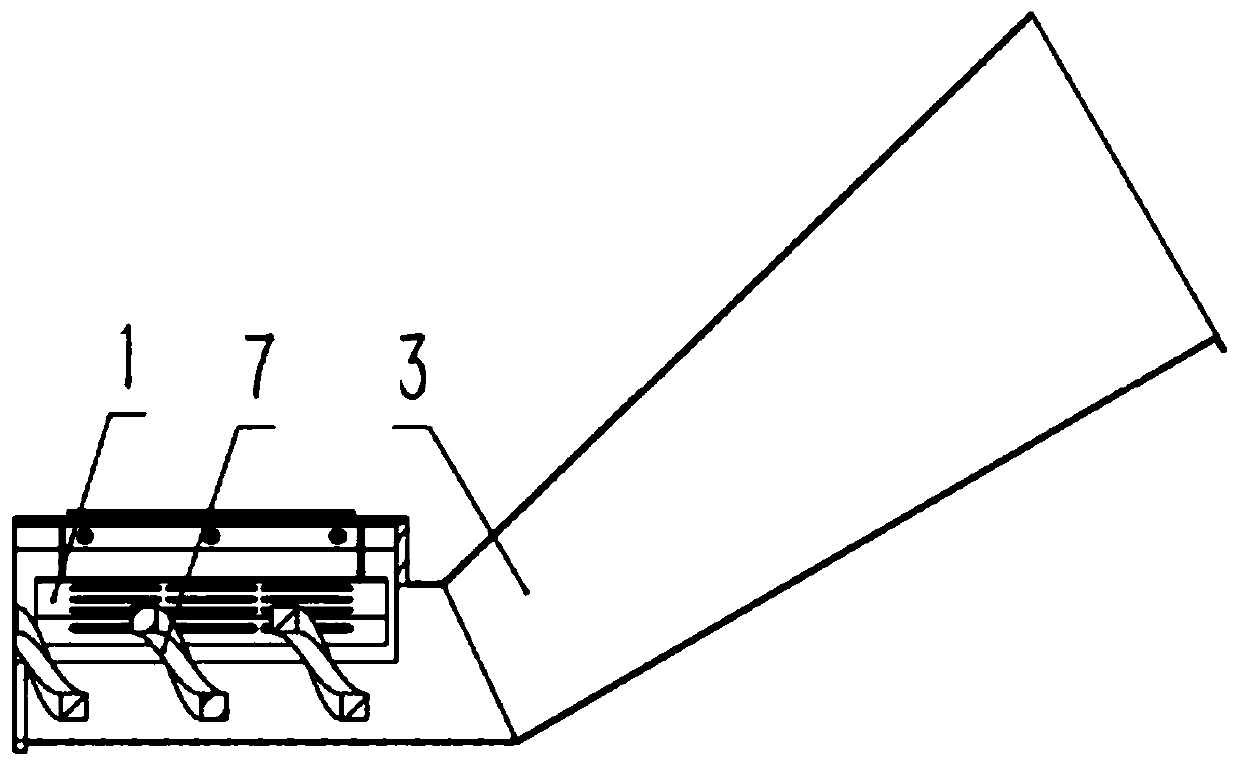
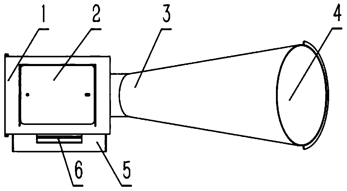
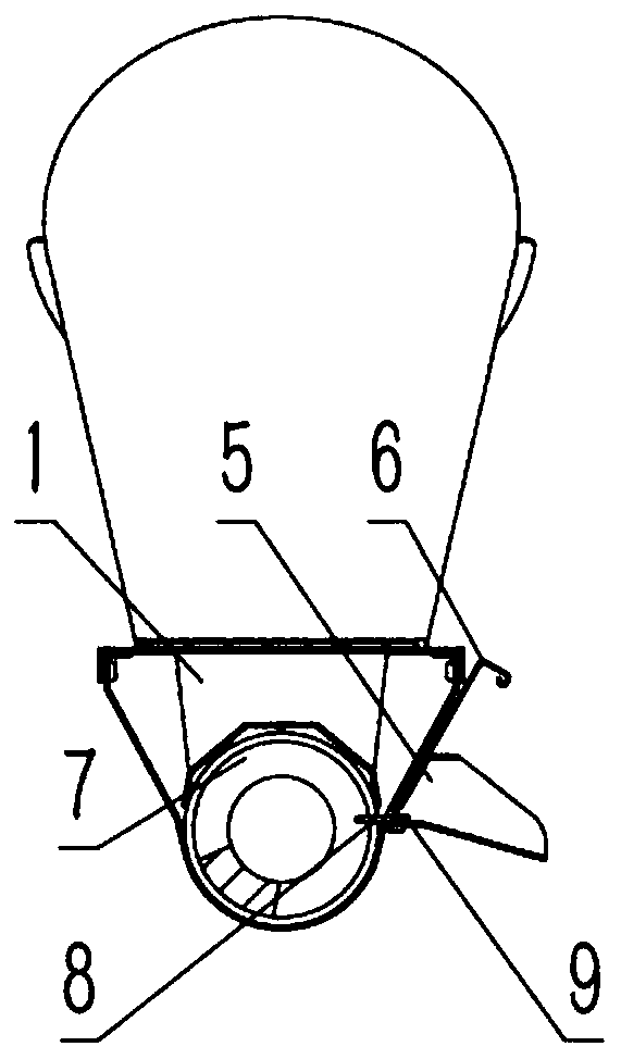
[0019] see Figure 1-4 , The chip removal elbow of the present invention includes a chip removal structure, a filtering structure and an observation structure.

[0020] The chip removal structure involves the filter guide cover 1, the elbow body 3, the chip outlet 4, the screw 7, the rubber scraper 8 and the rubber pressure plate 9, and the filter guide cover 1 is divided into the connecting part at the top and the filter guide part at the bottom The connection part on the top of the filter guide cover plate 1 is covered on the elbow body 3, the connection part and the elbow body are connected together by screws, and the top plate of the connection part is left with a rectangular hole, and there are bosses on three sides of the hole for Place the acrylic see-through plate 2; the filter guide part at the bottom is a cover surrounded by several sides of a regu...


PUM


Abstract

The invention relates to a scrap discharging elbow with scrap guiding, filtering and self-cleaning functions. The scrap discharging elbow with the scrap guiding, filtering and self-cleaning functionscomprises an elbow main body and a scrap outlet; one end of the elbow main body is connected with a scrap discharging elbow in a machine tool; the other end of the elbow main body is a scrap outlet which is opened upwards; a push screw rod is arranged in the scrap discharging groove in the machine tool; a filtering guide cover plate is arranged on the connecting part of the elbow main body and thescrap discharging groove in the machine tool; the filtering guide cover plate and the elbow main body form a rotating space of the push screw rod; the filtering guide cover plate comprises a connecting part at the top and a filtering guide part at the bottom; the connecting part and the elbow main body are connected together; the filtering guide part is a cover which is formed by splicing a cambered surface and a polygon to surround the push screw rod; a first strip-shaped hole is formed in the cover, can realize primary filtration on cutting liquid and also can generate guide effect on the scraps; an overflow type liquid outlet is formed in the side surface of the elbow main body; and a filtering baffle is arranged at the overflow type liquid outlet. The scrap discharging elbow providedby the invention is reasonable in structure, can discharge the scraps smoothly and output liquid cleanly, and greatly improves the on-site operation environment.

Description

technical field [0001] The invention belongs to the processing field of screw chip conveyors, and relates to a chip removal elbow with chip guiding, filtering and self-cleaning functions. Background technique [0002] The screw chip conveyor drives the screw in the groove to rotate through the motor through the reduction transmission device, and the screw pushes the chips so that the chips are discharged into the chip collection box. The screw chip conveyor is widely used in the field of CNC machine tool processing because of its small footprint and wide range of applicable chips. At present, many machine tools adopt a new bed structure in which the screw chip conveyor and the bed casting are integrated, which makes the screw chip conveyor more space-saving. The important indicators to measure the performance of the screw chip conveyor are the chip removal ability and the cleanliness of the liquid. The chip removal ability is to observe whether the waste chips can be smooth...

Claims


Application Information

Patent Timeline
Patent Type & Authority Applications(China)
IPC IPC(8): B23Q11/00B23Q11/10
CPCB23Q11/00B23Q11/10B23Q11/1069
Inventor 张保全赵金鹏李帅
Owner 西安精雕软件科技有限公司
Learn More