Seatbelt control device

A technology for control devices and seat belts, which is applied in the direction of seat belts, belt control systems, and pedestrian/passenger safety arrangements in vehicles, and can solve problems such as inability to switch between high loads and increased deceleration

Active Publication Date: 2019-10-01
TOYOTA JIDOSHA KK
View PDF5 Cites 1 Cited by
  • Summary
  • Abstract
  • Description
  • Claims
  • Application Information

AI Technical Summary

Problems solved by technology

Generally speaking, setting the force limiter mechanism to a low load is achieved by igniting a micro gas generator (MGG: microscale Gas Generator), so after temporarily setting the force limiter mechanism to a low load , even if the deceleration becomes larger after the elapse of time range A, switching to high load cannot be performed
Therefore, in the technology described in Japanese Patent Laid-Open No. 2009-190594, there is still room for improvement regarding the load control of the force limiter mechanism.

Method used


Image

  • Seatbelt control device
  • Seatbelt control device
  • Seatbelt control device

Examples


no. 1 approach

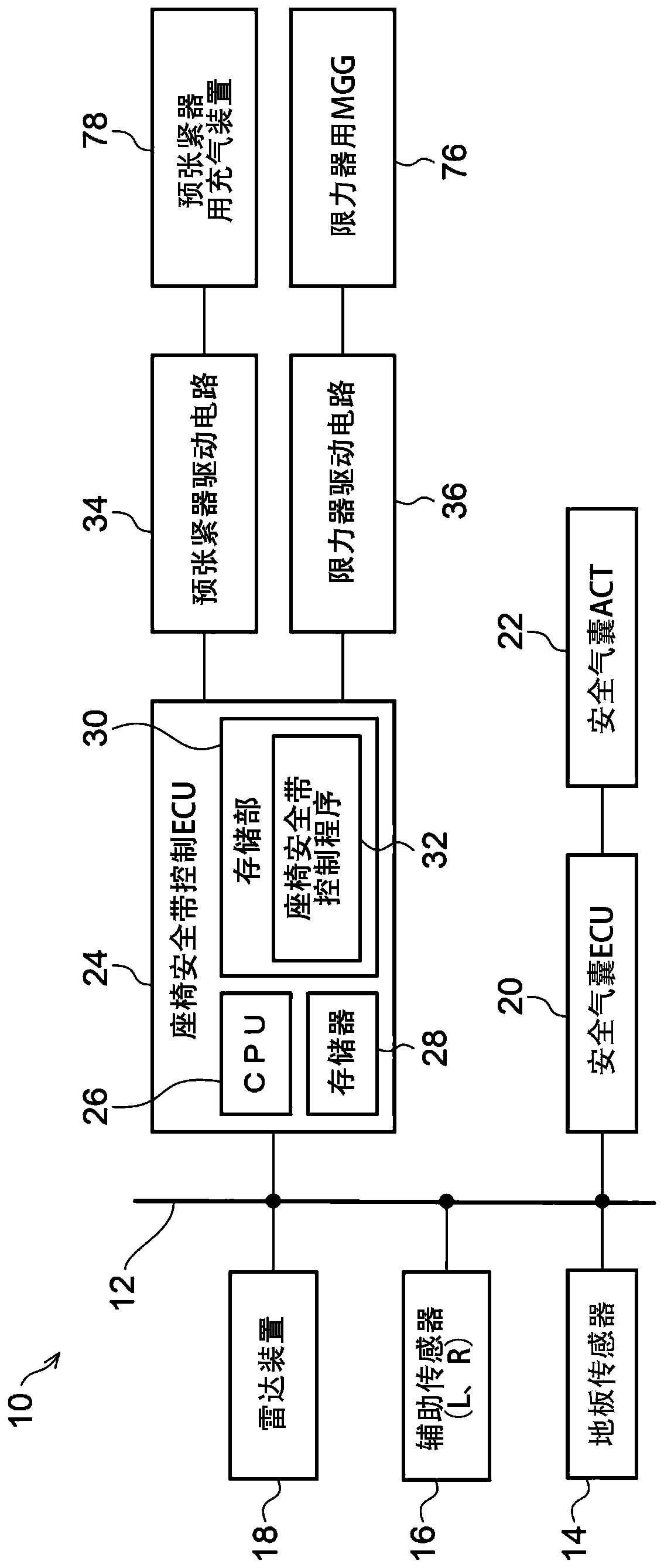
[0033] figure 1 The illustrated in-vehicle system 10 includes a bus 12 , and a plurality of sensor units and a plurality of electronic control units that perform different controls are connected to the bus 12 , respectively. in addition, figure 1 Only a portion of the onboard system 10 is shown. Each electronic control unit is a control unit including a CPU, a memory, and a nonvolatile storage unit, and is hereinafter referred to as an ECU (Electronic Control Unit: Electronic Control Unit). The plurality of sensor units connected to the bus 12 include the floor sensor 14, the auxiliary sensor 16, and the radar device 18, and the plurality of ECUs connected to the bus 12 include the airbag ECU 20 and the seat belt. Control ECU24.

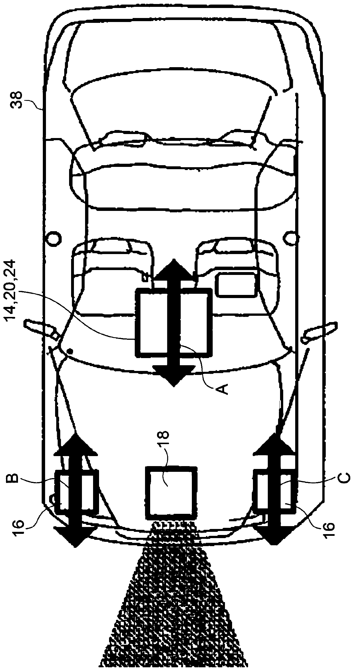
[0034] Such as figure 2 As shown, the floor sensor 14 is arranged in the passenger compartment of the vehicle 38 together with the air bag ECU 20 and the seat belt control ECU 24, and as in figure 2 As indicated by an arrow A in the figure, th...


PUM


Abstract

A seatbelt control device is provided. A seatbelt retractor device includes a pre-tensioner section retracting a seatbelt to increase tension; and a force limiter section that can change a magnitude of a load at which to start reducing tension of the seatbelt retracted by the pre-tensioner section. A seatbelt control ECU activates the pre-tensioner section when a deceleration G detected by a floorsensor exceeds a first threshold, acquires a collision velocity from a radar device and sets a second threshold value to a lower value the greater the collision velocity. The seatbelt control ECU controls the starting load for tension reduction by the force limiter section to be a high load when the deceleration G has exceeded the second threshold within a determination time period after activation of the pre-tensioner section, and controls the starting load for tension reduction to be a low load when the deceleration G has not exceeded the second threshold within the determination time period.

Description

technical field [0001] The present disclosure relates to a seat belt control device. Background technique [0002] In Japanese Patent Application Laid-Open No. 2009-190594, a technique is proposed in which a collision is discriminated based on the time range A after the deceleration of the vehicle exceeds a first threshold and the pretensioner mechanism starts operating. The load setting of the force limiter mechanism is switched according to whether the deceleration of the vehicle exceeds the second threshold. In this technique, the force limiter mechanism is set to a high load when the deceleration of the vehicle exceeds the second threshold value within the time range A, and the deceleration of the vehicle does not exceed the second threshold value within the time range A. In this case, the force limiter mechanism is set to low load when the time range A has elapsed. [0003] The temporal change of the deceleration that occurs when the vehicle collides with an object va...

Claims


Application Information

Patent Timeline
Patent Type & Authority Applications(China)
IPC IPC(8): B60R22/44B60R22/46B60R22/48
CPCB60R22/44B60R22/46B60R22/48B60R21/0132B60R2021/01272B60R2021/01279B60R2021/01322B60R21/01558B60R22/4676B60R2022/4685
Inventor 藤波贵司间瀬祐介
Owner TOYOTA JIDOSHA KK
Why Eureka
Try Eureka