Check patentability & draft patents in minutes with Patsnap Eureka AI!

flow totalizer

A flow totalizer and flow value technology, applied in the field of flow totalizers, can solve the problems that users cannot perceive the adjustment value in real time, cumbersome, and the setting value is not accurate enough.

Active Publication Date: 2020-10-27
北京晓韬科技有限公司
View PDF5 Cites 0 Cited by
  • Summary
  • Abstract
  • Description
  • Claims
  • Application Information

AI Technical Summary

Problems solved by technology

[0003] The way the knob drives the potentiometer, the set value is not accurate enough, the user can only know the current set value through the indicator dial of the knob, the accuracy error is about 10%; It can only be realized by pressing the button three times, and the user cannot perceive the current adjustment value in real time. Therefore, a flow totalizer is urgently needed to realize the function of simple operation and accurate adjustment, and at the same time, the user can view the adjustment value in real time.

Method used


Image

  • flow totalizer
  • flow totalizer

Examples


Embodiment Construction

[0045] In order to make the purpose, technical solution and advantages of the present invention clearer, the technical solution of the present invention will be described in detail below. Apparently, the described embodiments are only some of the embodiments of the present invention, but not all of them. Based on the embodiments of the present invention, all other implementations obtained by persons of ordinary skill in the art without making creative efforts fall within the protection scope of the present invention.

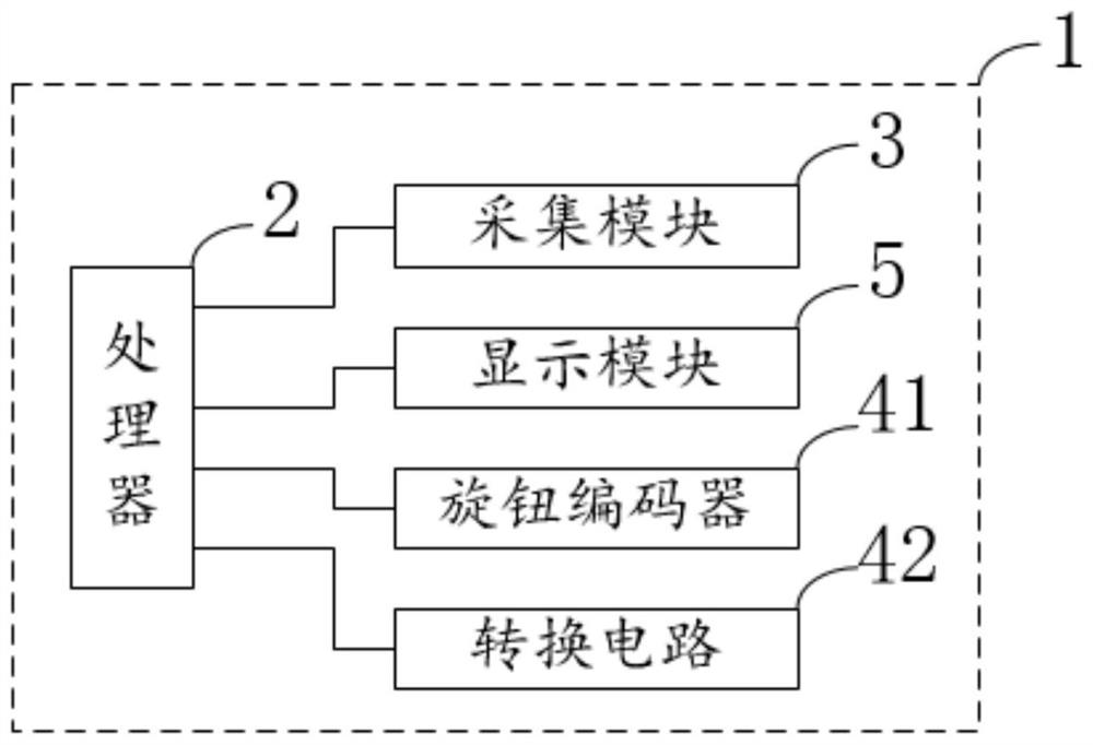
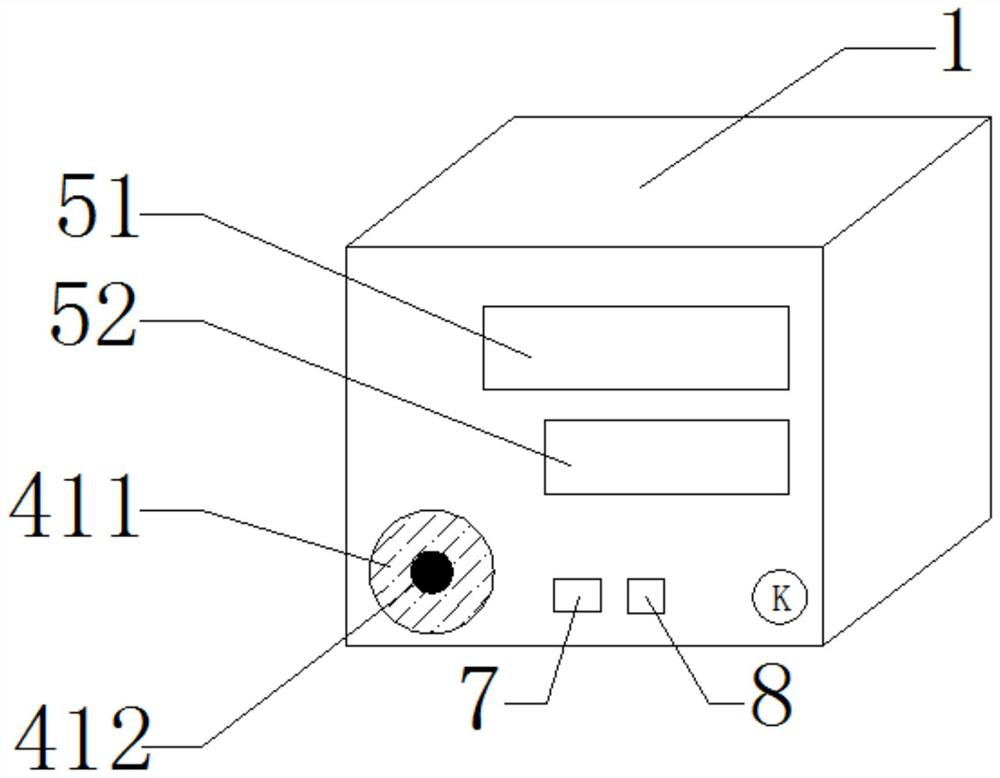
[0046] figure 1 It is a schematic diagram of the principle of the flow totalizer provided by the embodiment of the present invention. figure 2 It is a structural schematic diagram of the flow totalizer provided by the embodiment of the present invention.

[0047] figure 1 It is only a schematic diagram of the principle of the flow totalizer described, a schematic diagram of the principle of its circuit connection relationship, and a specific function of the ...


PUM


Abstract

The invention relates to a flow totalizer. The flow totalizer comprises a flow totalizer main body, a processor, a collection module, a regulating module and a display module; the regulating module comprises a rotary knob encoder and a conversion circuit; the conversion circuit is used for changing a working voltage of the rotary knob encoder; the rotary knob encoder is arranged on the flow totalizer main body and can displace in relative to the flow totalizer main body; when the rotary knob encoder is displaced to a first location, the conversion circuit converts the working voltage of the rotary knob encoder into the first voltage; when the rotary knob encoder is displaced to a second location, the conversion circuit converts the working voltage of the rotary knob encoder into the secondvoltage, the first voltage is greater than the second voltage, the conversion circuit changes regulation precision of the rotary knob encoder through the first voltage and the second voltage, the processor sets the regulating value range of the rotary knob encoder by controlling the value of the first voltage and the value of the second voltage; the operation is simpler and convenient, and the regulation is more precise.

Description

technical field [0001] The invention relates to the technical field of flow measurement and regulation, in particular to a flow totalizer. Background technique [0002] The flow totalizer is used for collection, display, control, remote transmission, communication, printing and other processing for various signals such as temperature, pressure and flow on site, and constitutes a digital collection system and control system. It is suitable for liquids, general gases, and superheated steam. , saturated steam, etc. flow integration measurement control. The user interaction form of the traditional flow totalizer is roughly divided into two types, one is to adjust the output voltage signal by driving the analog potentiometer with the knob, and the other is to adjust the output signal in the form of direct button selection. [0003] The way the knob drives the potentiometer, the set value is not accurate enough, the user can only know the current set value through the indicator d...

Claims


Application Information

Patent Timeline
Patent Type & Authority Patents(China)
IPC IPC(8): G01F15/075G05D7/06
CPCG01F15/075G05D7/0617G05D7/0635
Inventor 马弢牛晓杨健张福林
Owner 北京晓韬科技有限公司
Features
  • R&D
  • Intellectual Property
  • Life Sciences
  • Materials
  • Tech Scout
  • Unparalleled Data Quality
  • Higher Quality Content
  • 60% Fewer Hallucinations
Learn More