[0024] The technical solutions in the embodiments of the present invention will be clearly and completely described below in conjunction with the accompanying drawings in the embodiments of the present invention. Obviously, the described embodiments are only a part of the embodiments of the present invention, rather than all the embodiments. Based on the embodiments of the present invention, all other embodiments obtained by those of ordinary skill in the art without creative work shall fall within the protection scope of the present invention.
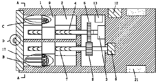
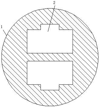
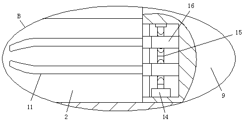
[0025] See Figure 1-5 , A medical surgical instrument, comprising an operating rod 1. The side wall of the operating rod 1 is provided with a circular groove, and the inner side wall of the circular groove is provided with two symmetrically arranged chutes 2 with a T-shaped cross section. A transmission cavity is provided. The inner side wall of the transmission cavity close to the chute 2 is provided with two rotation holes, and the two rotation holes are respectively communicated with the two chutes 2, and the inner side wall of the transmission cavity away from the chute 2 is fixedly connected with a drive motor 3 , The output shaft of the drive motor 3 is fixedly connected with a first threaded rod 4 through a coupling, the first threaded rod 4 is rotatably connected to one of the rotating holes through a bearing, and the end of the first threaded rod 4 away from the drive motor 3 extends into it Inside a chute 2, the first threaded rod 4 is fixedly sleeved with a first spur gear 5 on the side wall inside the transmission cavity. The inner side wall of the transmission cavity away from the chute 2 is provided with a T-shaped rotary groove. The inner wall of the groove is rotatably connected with a turntable 6, and the inner wall of the other hole is rotatably connected with a second threaded rod 7 through a bearing. One end of the second threaded rod 7 extends to the inside of the turn groove and is close to the side wall of the slide groove 2 with the turntable 6 Fixed connection, the other end of the second threaded rod 7 extends to the inside of the other chute 2, and the second threaded rod 7 is located on the side wall of the transmission cavity and is fixedly sleeved with a second spur gear meshing with the first spur gear 5 8. T-shaped sliding blocks 9 are slidably connected to the inside of the two sliding grooves 2, one of the sliding blocks 9 away from the side wall of the driving motor 3 is fixedly connected with the cutter 10, and the other sliding block 9 is away from the side wall of the driving motor 3 A transmission groove with a T-shaped section is provided. The inside of the transmission groove is connected with two symmetrically arranged clamping plates 11 through a transmission mechanism. One end of the two clamping plates 11 extends to the outside of the transmission groove, and the side of the operating rod 1 The wall is provided with a mounting groove, the inside of the mounting groove is fixedly embedded with a display screen 12 that matches the mounting groove, the inner top of the transmission cavity is fixedly connected with a controller 13, and the driving motor 3 and the display screen 12 are connected to the controller 13 through wires For signal connection, a sealing mechanism corresponding to the two sliding grooves 2 is arranged inside the circular groove.
[0026] The transmission mechanism includes a transmission motor 14. The transmission motor 14 is fixedly connected to the inner bottom of the transmission groove. The transmission motor 14 is signally connected to the controller 13 through a wire. The end of the output shaft of the transmission motor 14 is fixedly connected with a bidirectional screw 15 through a coupling. The end of the bidirectional screw 15 away from the transmission motor 14 is rotatably connected to the inner top of the transmission groove through a bearing. Two symmetrically arranged transmission blocks 16 are slidably connected to the inside of the transmission groove. The two transmission blocks 16 are respectively connected with two of the bidirectional screw 15 The two clamping plates 11 close to the side walls of the transmission cavity are respectively fixedly connected to the side walls of the two transmission blocks 16. When the doctor needs to use the two clamping plates 11, the display screen 12 and the controller 13 can The driving motor 3 rotates in the reverse direction. At this time, one of the sliders 9 drives the cutter 10 to extend and move closer to the drive motor 3, and the other slider 9 drives the two clamping plates 11 to move away from the drive motor 3. When the two clamping plates 11 are located outside the chute 2, the drive motor 14 is controlled by the display 12 and the controller 13 to drive the two-way screw 15 to rotate in the forward or reverse direction. When the two-way screw 15 rotates in the forward direction At this time, the two clamping plates 11 move close together until the ends of the two clamping plates 11 away from the transmission motor 14 clamp other tools. There is no need for the doctor to use force to clamp other tools with tweezers. When the two-way screw 15 rotates in the reverse direction, the two clamping plates 11 move away from each other, and the two clamping plates 11 loosen other clamped tools. The operation is simple and convenient for doctors to use.
[0027] The sealing mechanism includes a cover plate 17 that matches the circular groove. The inner wall of the circular groove is provided with internal threads. The side wall of the cover plate 17 is provided with external threads that match the internal threads. The cover plate 17 is threadedly connected with the circular groove. 17 The side wall far from the drive motor 3 is fixedly connected with a semi-circular handle 18, the side wall of the handle 18 is fixedly sleeved with a rubber sleeve 19, and the outer side wall of the rubber sleeve 19 is provided with anti-skid patterns. When the cutter 10 and When the two clamping plates 11 are used, the cover plate 17 is threadedly connected with the circular groove, so that the cutter 10 and the two clamping plates 11 are in a closed space, thereby effectively preventing dust from contaminating the cutter 10 and the clamping plate 11.
[0028] One of the sliding blocks 9 is provided with a threaded hole on the side wall away from the first spur gear 5, and the cutter 10 is fixedly connected to the side wall of the first spur gear 5 with a third threaded rod 20 matching the threaded hole. 20 is threadedly connected with the threaded hole, and the third threaded rod 20 is used in conjunction with the threaded hole, which is convenient for the doctor to change the cutter 10 of different specifications for use.
[0029] The side wall of the operating rod 1 is provided with a ring-shaped accommodating groove. The inside of the accommodating groove is fixedly sleeved with a non-slip sleeve 21. The outer side wall of the non-slip sleeve 21 is provided with anti-slip patterns. The material of the anti-slip sleeve 21 is rubber. The drive motor 3 and the transmission motor 14 are all servo motors.
[0030] In summary, the medical surgical instrument is provided with a display screen 12. When the doctor needs to use the cutter 10, the drive motor 3 is controlled to rotate forward through the display screen 12 and the controller 13. At this time, the first threaded rod 4 And the first spur gear 5 drives the second spur gear 8 and the second threaded rod 7 to rotate, so that one of the sliders 9 drives the cutter 10 to move away from the drive motor 3, and the other slider 9 drives the two clamping plates 11 When the cutting knife 10 is completely outside the chute 2, the doctor can operate the cutting knife 10 through the operating rod 1. When the doctor needs to use two clamping plates 11, use the display 12 and control The drive 13 makes the drive motor 3 rotate in the reverse direction. At this time, one of the sliders 9 drives the cutter 10 to extend and move closer to the drive motor 3, and the other slide 9 drives the two clamping plates 11 to move away from the drive motor 3. When the two clamping plates 11 are located outside the chute 2, the drive motor 14 is controlled by the display screen 12 and the controller 13 to drive the two-way screw 15 to rotate in the forward or reverse direction. When rotating forward, the two clamping plates 11 move closer together until the end of the two clamping plates 11 away from the transmission motor 14 clamps other tools, without the doctor using his own force to clamp other tools with tweezers , And when the two-way screw 15 rotates in the reverse direction, the two clamping plates 11 move away from each other, and the two clamping plates 11 loosen other clamped tools. The operation is simple and convenient for doctors to use. Mechanism, when the cutter 10 and the two clamping plates 11 are not needed, the cover plate 17 is screwed with the circular groove, so that the cutter 10 and the two clamping plates 11 are in a closed space, thereby effectively avoiding dust pollution Cutter 10 and clamping plate 11.
[0031] Although the embodiments of the present invention have been shown and described, those of ordinary skill in the art can understand that various changes, modifications, and substitutions can be made to these embodiments without departing from the principle and spirit of the present invention. And variations, the scope of the present invention is defined by the appended claims and their equivalents.