Two-piston and four-chamber supercharged tool release oil cylinder

A technology of loosening the knife and oil cylinder, applied in the direction of clamping, supporting, positioning devices, etc., which can solve the problems of small thrust and unsuitable for large-scale machining centers, and achieve the effect of large thrust and small overcoming thrust

Pending Publication Date: 2019-10-08
CHANGZHOU INST OF MECHATRONIC TECH
View PDF1 Cites 0 Cited by
  • Summary
  • Abstract
  • Description
  • Claims
  • Application Information

AI Technical Summary

Problems solved by technology

[0003] In the specific use process, it is found that there are still at least the following deficiencies. When the oil cylinder in the prior art pushes the piston rod from the hydraulic oil inlet, because i

Method used


Image

  • Two-piston and four-chamber supercharged tool release oil cylinder
  • Two-piston and four-chamber supercharged tool release oil cylinder
  • Two-piston and four-chamber supercharged tool release oil cylinder

Examples


Embodiment 1

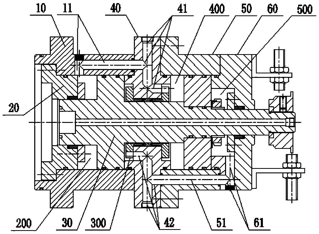
[0044] like figure 1 , figure 2 , image 3 , Figure 4 , Figure 5 , Image 6 , Figure 7 , Figure 8 Shown; A kind of two-plug four-chamber supercharged loose knife oil cylinder, comprises:

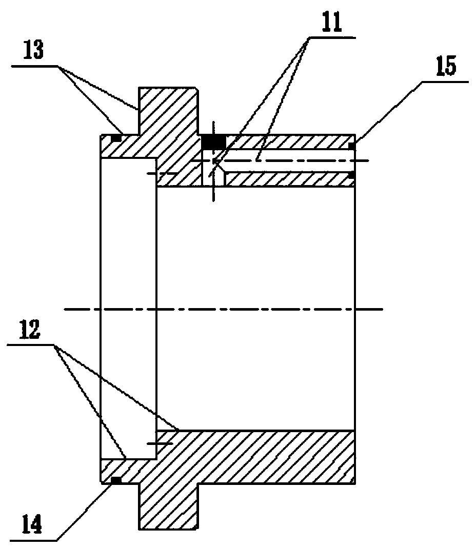
[0045] A first shell member 10, connected to the main shaft 1000, has a first oil passage 11 on the side wall;

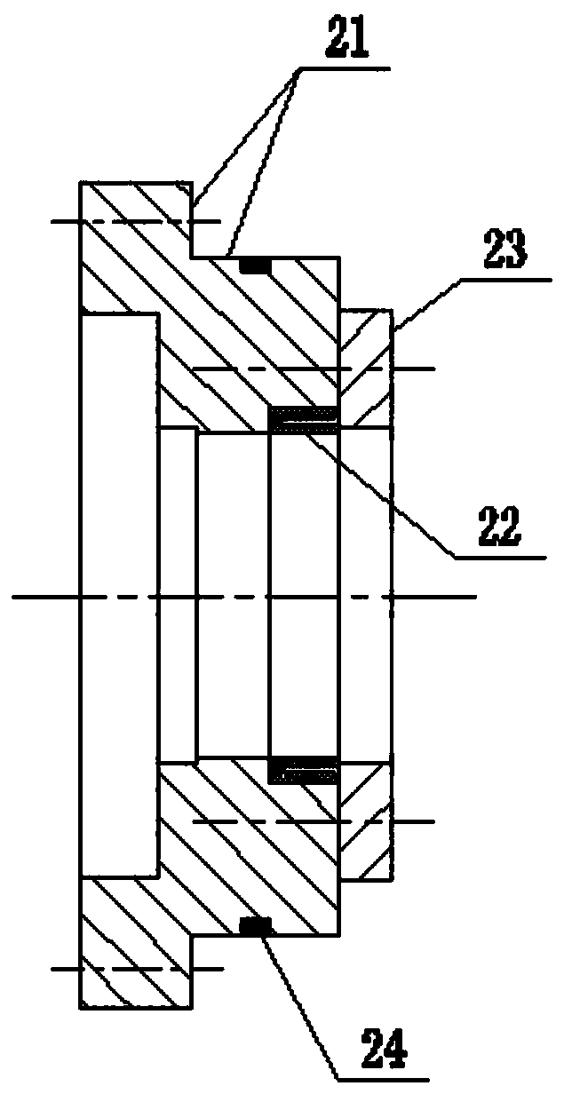
[0046] a first stopper 20, fitted in the first housing member 10, and close to the main shaft 1000;

[0047]A piston member 30, one end of which is matched with the inner wall of the first housing member 10, and can pass through the first stopper 20, and move back and forth along the first housing member 10 and the first stopper 20 , forming a first cavity 200 between the first housing member 10 and the first stopper 20; the first cavity 200 communicates with the first oil passage 11;

[0048] A barrier member 40 has a second oil channel 41 and a third oil channel 42 on the side wall, sleeved on the piston member 30 and connected with the first housing member 10, and...

Embodiment 2

[0102] like figure 1 , Figure 4 , Figure 8 As shown; on the basis of Embodiment 1, the central part of the piston member 30 is also provided with a stepped through hole 37;

[0103] The stepped through hole 37 includes an internally threaded hole for connecting a connecting pipe with an external thread; a long through hole connected to the internally threaded hole; and a short through hole connected to the long through hole; The inner diameter of the short through hole is more than twice the inner diameter of the long through hole, which can gather more air;

[0104] During implementation, through connecting pipes with external threads, connecting hoses, passing air into the stepped through hole 37, the circulating air can take away heat, thereby reducing the pressure on the two-plug four-chamber pressurized loosening cylinder and the main shaft. The temperature has the effect of cooling down;

Embodiment 3

[0106] like figure 1 , Figure 8 As shown; on the basis of the second embodiment, a contact piece 38 is also provided on the end of the piston member 30; a first non-contact switch 39 and a second non-contact switch 39 are also provided on the side wall of the second stopper 60 Non-contact switches 391 are respectively used to cooperate with the contacts 38;

[0107] During implementation, the contact piece 38 includes a shaft sleeve, which is threaded on the external thread section at one end of the stepped shaft 31; The non-contact switch 39 and the second non-contact switch 391 are used;

[0108] The first non-contact switch 39 and the second non-contact switch 391 are structures in the prior art, such as KZ-H360ZF type; the distance from the second non-contact switch 391 to the side wall of the second stopper 60 , greater than the distance from the first non-contact switch 39 to the side wall of the second stopper 60;

[0109] When the annular flange on the contact pie...


PUM


Abstract

The invention discloses a two-piston and four-chamber supercharged tool release oil cylinder. The oil cylinder comprises a first casing part connected onto a spindle, a first stop part, a piston part,a blocking part, a second casing part and a second stop part, wherein a first oil channel is formed on the side wall of the first casing part; the first stop part is arranged in the first casing partin a matched manner; one end of the piston part is matched with the inner wall of the first casing part and can penetrate through the first stop part, and a first chamber is formed among the piston rod, the first casing part and the first stop part; a second oil channel and a third oil channel are formed in the side wall of the blocking part, the blocking part is arranged on the piston part in asleeving manner and connected with the first casing part, and a second chamber is formed among the blocking part, the piston part and the first casing part; a fourth oil channel is formed on the sidewall of the second casing part, the second casing part is connected onto the blocking part and arranged on the piston part in a sleeving manner, and a third chamber is formed among the second casing part, the blocking part and the piston rod; a fifth oil channel is formed in the side wall of the second stop part, the second stop part is connected onto the second casing part and arranged on the piston part in a sleeving manner, and a fourth chamber is formed among the second stop part, the second casing part and the piston part. Therefore, the technical problem of smaller thrust is solved.

Description

technical field [0001] The invention relates to the technical field of oil cylinders in the main shaft structure of a large machining center, in particular to a two-plug four-cavity pressurized tool loosening oil cylinder. Background technique [0002] The main shaft structure of a large machining center generally includes a main shaft housing, a main shaft connected to the main shaft housing, a broaching claw structure passing through the main shaft for positioning the tool, and a pull rod connected to the main shaft to push the broaching claw structure action, so that the pulling claw structure releases the oil cylinder of the knife; for example, the Chinese patent application number is 201420353376.6, and the subject name of the patent is the prior art of the loose knife cylinder. The hydraulic oil enters the cavity from the hydraulic oil inlet, and the hydraulic oil pushes the piston body along the The accommodating space moves downward, the piston rod moves to a certain...

Claims


Application Information

Patent Timeline
IPC IPC(8): B23Q3/12
CPCB23Q3/12B23Q2703/04
Inventor 周保牛
Owner CHANGZHOU INST OF MECHATRONIC TECH
Why Eureka
Try Eureka