Handling system, control method thereof and floor tile laying system

A technology of a handling system and a control method, applied in the field of robots, can solve the problem that the robot cannot meet the requirements of tiling accuracy.

Active Publication Date: 2019-10-08
GUANGDONG BOZHILIN ROBOT CO LTD
View PDF7 Cites 8 Cited by
  • Summary
  • Abstract
  • Description
  • Claims
  • Application Information

AI Technical Summary

Problems solved by technology

[0005] Embodiments of the present invention provide a handling system and its control method, and a floor tile laying system, so as to at least solve the technical problem that the robot used for laying tiles in the prior art cannot meet the accuracy requirements for laying tiles

Method used


Image

  • Handling system, control method thereof and floor tile laying system
  • Handling system, control method thereof and floor tile laying system
  • Handling system, control method thereof and floor tile laying system

Examples


Embodiment 1

[0036] According to an embodiment of the present invention, an embodiment of a method for controlling a handling system is provided. It should be noted that the steps shown in the flowcharts of the accompanying drawings can be executed in a computer system such as a set of computer-executable instructions, and , although a logical order is shown in the flowcharts, in some cases the steps shown or described may be performed in an order different from that shown or described herein.

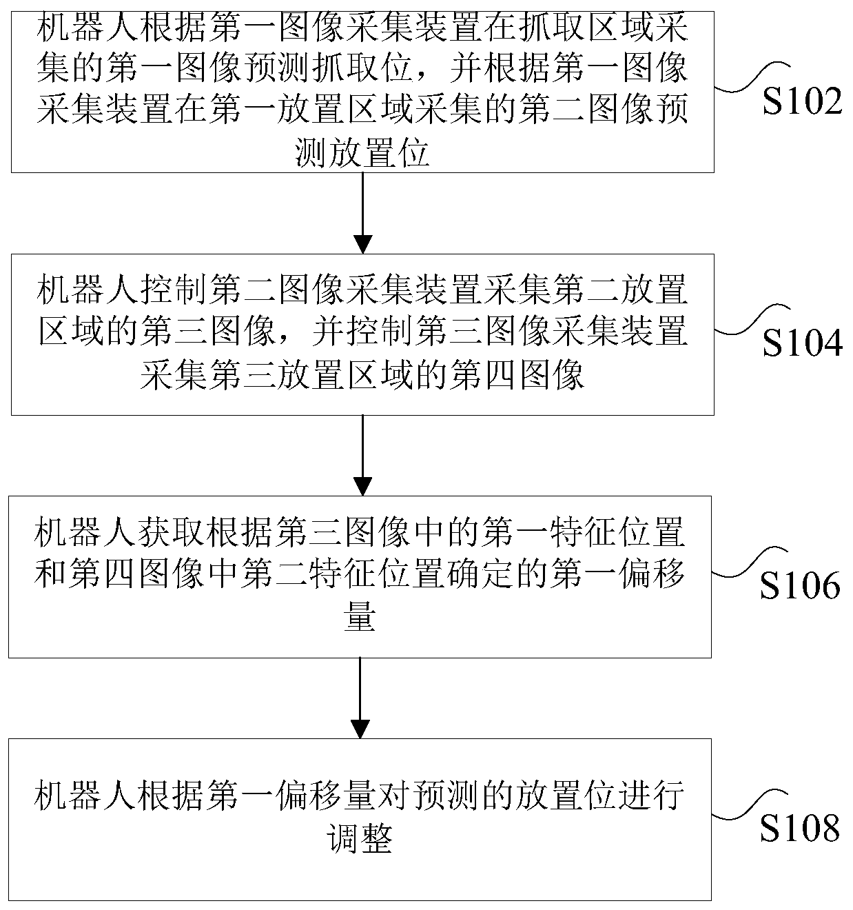
[0037] figure 1 It is a flowchart of a control method of a transport system according to an embodiment of the present application, and the transport system includes: a first image acquisition device, a second image acquisition device, a third image acquisition device and a robot, such as figure 1 As shown, the method includes the following steps:

[0038] Step S102, the robot predicts the grasping position according to the first image captured by the first image capture device in the grasping area...

Embodiment 2

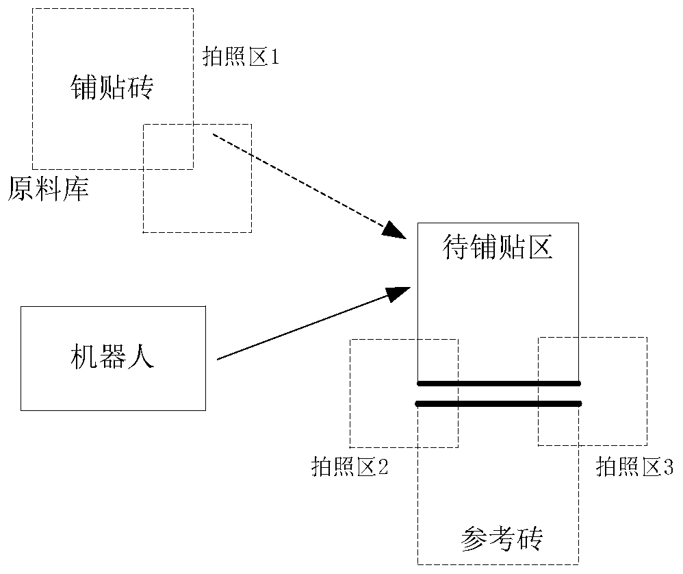
[0093] The embodiment of the present application also provides a transport system, which may be a system that performs any step in Embodiment 1. Figure 5 is a schematic diagram of a handling system according to an embodiment of the present application, combined with Figure 5 As shown, the system includes:

[0094] The first image acquisition device 10 is configured to acquire a first image in the grasping area and a second image acquired in the first placing area, predict the grasping position according to the first image, and predict the placing position according to the second image.

[0095] Specifically, the above-mentioned image acquisition devices may all be smart cameras, wherein the first image acquisition device may be a smart camera arranged at the end of the mechanical arm. The robot may include a pole, and the second image acquisition device and the third image acquisition device are arranged at the end of the pole.

[0096]In an optional embodiment, taking the...

Embodiment 3

[0137] According to an embodiment of the present invention, an embodiment of a control method of a transport system is provided, Figure 9 is a flow chart of another control method for a transport system according to an embodiment of the present application, combined with Figure 9 As shown, the method includes:

[0138] Step S902, predicting the grabbing position according to the first image collected in the grabbing area, and predicting the placement position according to the first placement area.

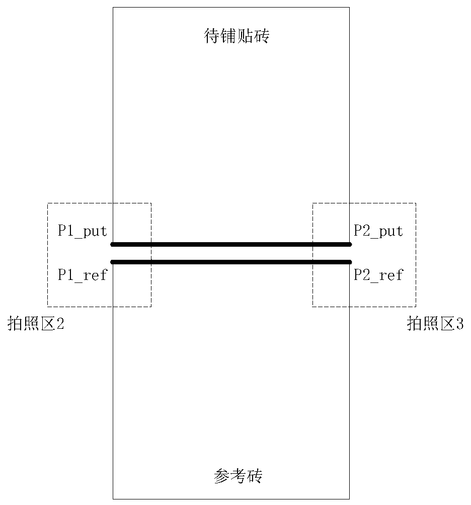
[0139] Step S904, acquiring a third image of the second placement area and a fourth image of the third placement area, wherein the second placement area and the third placement area include two different characteristic positions of the placed object.

[0140] Step S906, the first offset determined according to the first feature position in the third image and the second feature position in the fourth image, wherein the first offset is used to represent the deviation between the ...


PUM


Abstract

The invention discloses a handling system, a control method thereof and a floor tile laying system. The control method of the handling system comprises the following steps: a robot predicts a grabbingposition according to a first image acquired by a first image acquisition device in a grabbing area, and predicts a placing position according to a second image acquired by the first image acquisition device in a first placing area; the robot controls a second image acquisition device to acquire a third image of a second placing area, and controls a third image acquisition device to acquire a fourth image of a third placing area, wherein the second placing area and the third placing area comprise two different feature positions of a placed object; the robot acquires a first offset determinedaccording to the first feature position in the third image and the second feature position in the fourth image, wherein the first offset is used for representing the deviation of the actual placing position from the predicted placing position; the robot adjusts the predicted placing position based on the first offset. According to the invention, the technical problem that the robot for laying floor tiles in the prior art cannot meet the laying precision requirement is solved.

Description

technical field [0001] The invention relates to the field of robots, in particular to a handling system, a control method thereof, and a floor tile laying system. Background technique [0002] Tiling has a wide range of applications in the field of construction. At present, the work of tiling is usually carried out manually. Manual measurement is usually inaccurate, and the construction progress is slow. Therefore, in the field of tiling, robots are gradually introduced. [0003] During the process of laying floor tiles, the current tile-laying robot grabs the floor tiles from the AGV (Automated Guided Vehicle), transports them to the laying position, aligns the reference bricks, and then lays the floor tiles. However, due to the limited positioning accuracy of AGV (error 20mm), and the paving of floor tiles has high requirements for accuracy, it is difficult for this method to meet the accuracy requirements of paving and pasting of floor tiles. [0004] Aiming at the probl...

Claims


Application Information

Patent Timeline
Patent Type & Authority Applications(China)
IPC IPC(8): B25J9/16B25J15/06B25J19/02E04F21/22
CPCB25J9/1602B25J9/1697B25J15/0683B25J19/023E04F21/22
Inventor 汪亚伦刘震李江黎威
Owner GUANGDONG BOZHILIN ROBOT CO LTD
Why Eureka
Try Eureka