Short pier rigid-frame bridge pier bottom structure with function of greatly reducing bearing bending moment

A large-scale, rigid-frame bridge technology, used in bridges, bridge construction, bridge parts, etc., can solve the problems of affecting structural durability, large bending moment at the bottom of piers, cracking of bridge piers, etc., to ensure safety, durability and quality. Guaranteed reliability, release shrinkage and creep effects

Pending Publication Date: 2019-10-08
CHINA RAILWAY ERYUAN ENG GRP CO LTD
View PDF0 Cites 1 Cited by
  • Summary
  • Abstract
  • Description
  • Claims
  • Application Information

AI Technical Summary

Problems solved by technology

[0004] Due to the characteristics of the continuous rigid frame bridge, if it is built on some complex terrain with short pier, the pier will bear a large bending moment, resulting in very serious cracking of the pier
The biggest disadvantage of rigid frame bridges with low piers is that the bottom of the pier bears a large bending moment, and the tensile stress of the concrete exceeds its tensile strength, resulting in cracks that affect the durability of the structure.

Method used


Image

  • Short pier rigid-frame bridge pier bottom structure with function of greatly reducing bearing bending moment
  • Short pier rigid-frame bridge pier bottom structure with function of greatly reducing bearing bending moment
  • Short pier rigid-frame bridge pier bottom structure with function of greatly reducing bearing bending moment

Examples


Embodiment Construction

[0026] The present invention will be further described below in conjunction with the accompanying drawings and embodiments.

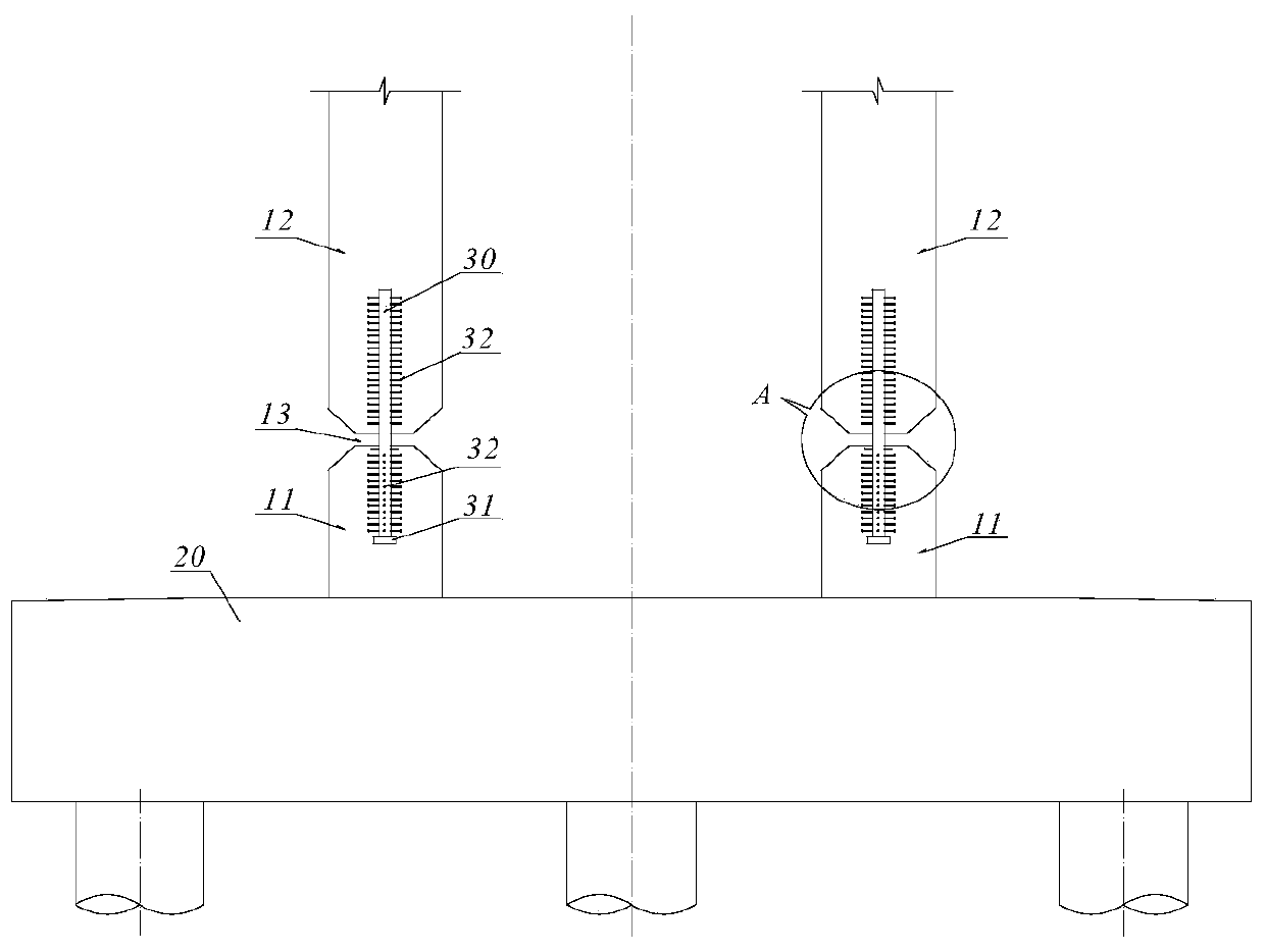
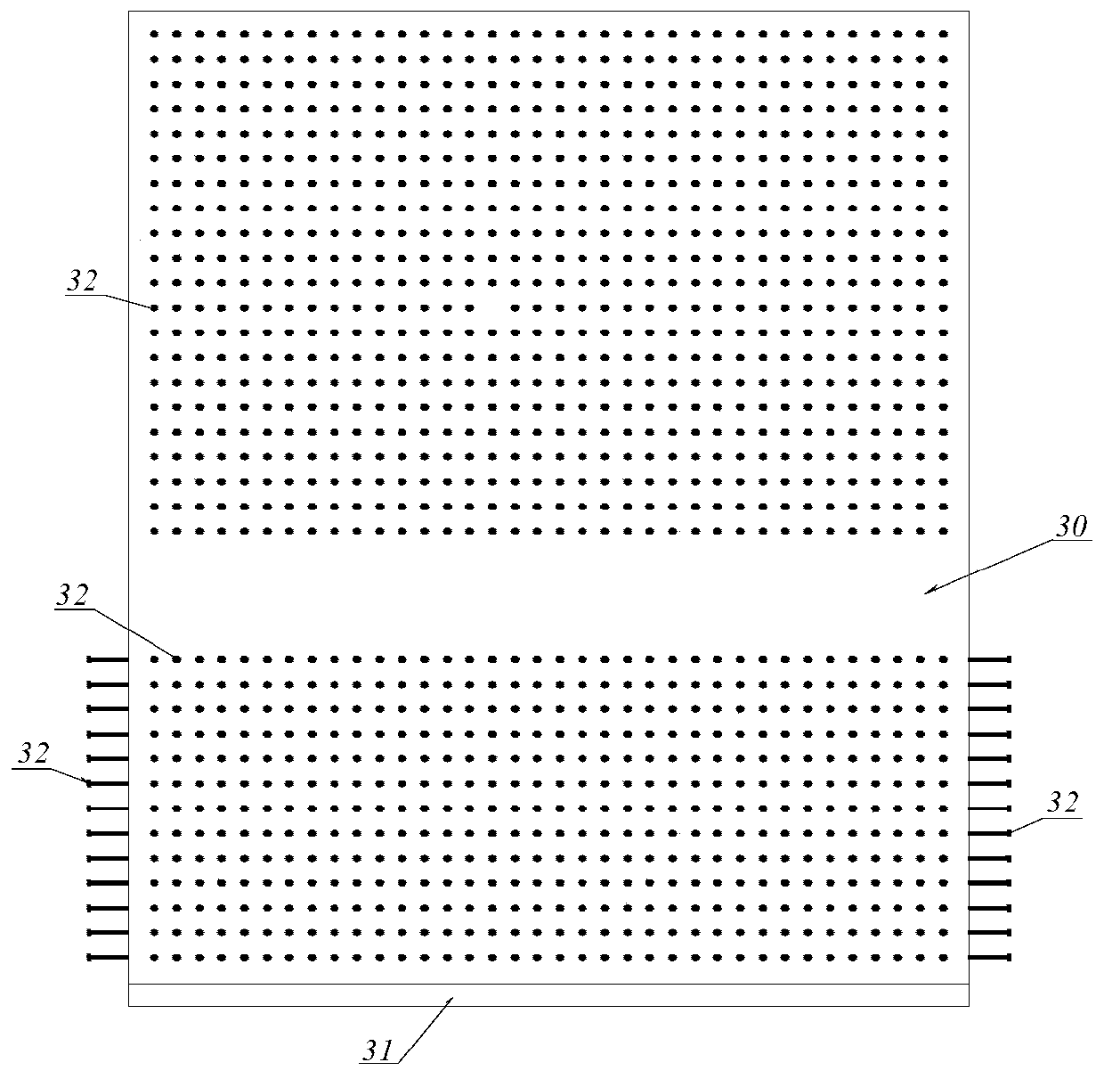
[0027] refer to figure 1 and figure 2 , the pier bottom structure of the low-pier rigid-frame bridge that can greatly reduce the bending moment of the present invention includes a bridge pier and a foundation cap 20, and the upper and lower ends of the bridge pier are respectively consolidated with the bridge girder and the foundation cap 20. The pier is broken into two sections, the upper pier 12 and the lower pier 11 adjacent to the bottom of the pier, and an annular seam 13 is formed between the corresponding end surfaces of the upper pier 12 and the lower pier 11 . Between the upper pier 12 and the lower pier 11, a steel plate hinge bearing vertical axial force is arranged, and the steel plate hinge vertically extends into the upper pier 12 and the lower pier 11 and is consolidated therewith. refer to image 3 , there is an annular seam 13 betwe...


PUM

PropertyMeasurementUnit
Heightaaaaaaaaaa

Abstract

The invention discloses a short pier rigid-frame bridge pier bottom structure with a function of greatly reducing bearing bending moment. According to the short pier rigid-frame bridge pier bottom structure, shrinkage and creep of concrete are greatly reduced, the section bending moment near the short pier rigid-frame bridge pier bottom under the temperature effect and the live load action is greatly reduced, cracking of the concrete near the pier bottom of the short pier is avoided, or, the crack width of the concrete is greatly reduced, the durability of the structure is guaranteed, and theapplication range of the continuous rigid-frame bridge is enlarged. The short pier rigid-frame bridge pier bottom comprises a bridge pier and a foundation bearing platform, the upper end and the lowerend of the bridge pier are fixedly connected with a bridge main beam and the foundation bearing platform correspondingly, and the short pier rigid-frame bridge pier bottom structure is characterizedin that the bridge pier is disconnected at a position near the pier bottom to form two sections, namely, a bridge pier upper portion and a bridge pier lower portion, a circular seam is formed betweenthe corresponding end faces of the bridge pier upper portion and the bridge pier lower portion, a steel plate hinge for bearing vertical axial force is arranged between the bridge pier upper portion and the bridge pier lower portion, and the steel plate hinge extends into the bridge pier upper portion and the bridge pier lower portion in the vertical direction in a fixedly connected mode.

Description

technical field [0001] The invention belongs to the technical field of bridge engineering, in particular to a pier bottom structure of a low-pier rigid-frame bridge that can greatly reduce the bending moment. Background technique [0002] In recent years, with the development of my country's transportation industry, people have put forward higher and higher requirements for bridge engineering. Because the continuous rigid frame bridge has no support for the main girder and pier, it not only reduces the bending moment of the main girder, but also the main It is widely constructed because of the advantages of large-tonnage bearings that do not need to be used between piers and girders. However, compared with continuous beams, continuous rigid frame bridges require a higher pier height, otherwise the bending moment at the bottom of the pier after the main girder and pier are rigidly connected will be particularly large, which will cause the concrete of the pier to crack due to t...

Claims


Application Information

Patent Timeline
IPC IPC(8): E01D19/02
CPCE01D19/02
Inventor 王应良王克思杨文慧
Owner CHINA RAILWAY ERYUAN ENG GRP CO LTD
Why Eureka
Try Eureka