
Assembling type steel structure residence system and node installation method thereof

A steel structure, prefabricated technology, applied in residential construction, building structure, construction, etc., can solve the problems of inconvenient promotion of prefabricated steel structures, difficult to guarantee welding quality, and high requirements for welding personnel, and achieves fast construction speed and construction. Guaranteed quality and reduced number of bolted connections

Pending Publication Date: 2019-10-08
上海泰大建筑科技有限公司
View PDF0 Cites 4 Cited by
  • Summary
  • Abstract
  • Description
  • Claims
  • Application Information

AI Technical Summary

Problems solved by technology

[0002] Existing steel structure residences generally adopt a frame structure system with or without lateral support. The column section of this structural system is generally large, and exposed steel beams and columns can be seen indoors. Compared with non-protruding walls In terms of the concrete shear wall structure on the surface, it is difficult for residents to accept; in addition, the existing steel structure houses are mostly connected by bolt welding at the frame joints, the installation speed is slow, the quality of on-site welding is difficult to guarantee, and the requirements for welding personnel are high, which is inconvenient. Promotion of prefabricated steel structures; In addition, in the existing frame system that uses bolt connections, generally the upper and lower flanges and webs need to be provided with gusset plates, and the bolts protrude from the top surface of the beam on the upper flange, which affects the floor installation, and the number of bolts big, expensive

Method used


Image

  • Assembling type steel structure residence system and node installation method thereof
  • Assembling type steel structure residence system and node installation method thereof
  • Assembling type steel structure residence system and node installation method thereof

Examples


Embodiment Construction

[0028] Detailed specific embodiments of the present invention will be disclosed herein. It is to be understood, however, that the disclosed embodiments are merely typical examples of the invention, which may be embodied in many alternative forms. Therefore, specific structural and functional details disclosed herein are not limiting, but merely serve as a representative basis for describing various implementations to one skilled in the art in accordance with the claims.

[0029] In order to facilitate the understanding of the present invention, the following will be described in conjunction with the accompanying drawings and embodiments.

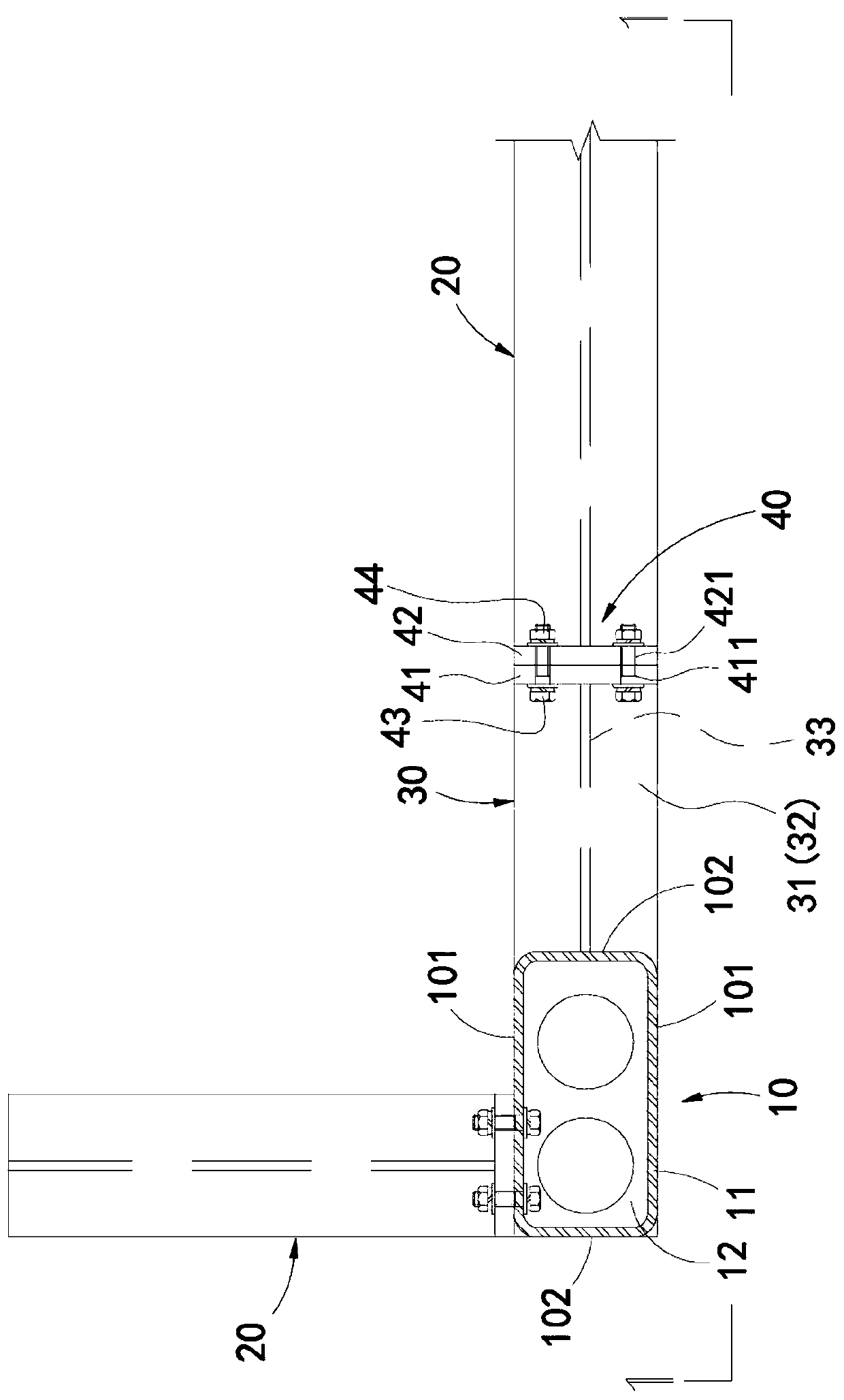
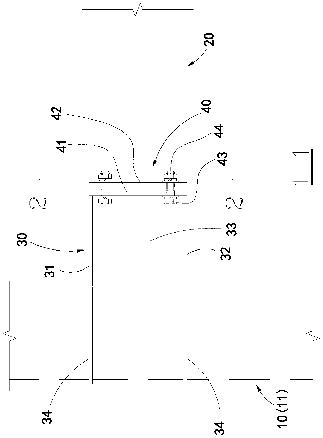
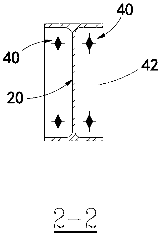
[0030] The invention provides an assembled steel structure residential system and a node installation method thereof. The prefabricated steel structure residential system of the present invention mainly includes a steel structure, a wall body, and a floor slab; the beams and columns of the steel structure are hidden in the wall, and the bea...


PUM


Abstract

The invention provides an assembling type steel structure residence system and a node installation method thereof. Steel column components with wide-flat shape rectangular steel pipes as main body constitution is arranged in corner positions and the middle of the residence, wherein cross section width of the steel pipes is larger than or equal to wall thickness, and cross section length of the steel pipes is longer, and a narrow column structure is formed; and the purpose of hiding steel columns in walls is achieved so that lateral support is not needed to be arranged additionally in the longitudinal direction in the residence. In addition, corbels arranged along the plane long edge extension direction of the residence are arranged on the steel column components in a matched manner, and nodes are moved outside from the steel column components by the corbels. Moreover, connection installation of steel beam components and the steel column components or connection installation of the steel beam components and the corbels is conducted through a bolt assembly, and the purpose of minimization of onsite welding work is achieved.

Description

technical field [0001] The invention relates to the technical field of building structure design and construction, in particular to a prefabricated steel structure residential system and a node installation method thereof. Background technique [0002] Existing steel structure residences generally adopt a frame structure system with or without lateral support. The column section of this structural system is generally large, and exposed steel beams and columns can be seen indoors. Compared with non-protruding walls In terms of the concrete shear wall structure on the surface, it is difficult for residents to accept; in addition, the existing steel structure houses are mostly connected by bolt welding at the frame joints, the installation speed is slow, the quality of on-site welding is difficult to guarantee, and the requirements for welding personnel are high, which is inconvenient. Promotion of prefabricated steel structures; In addition, in the existing frame system that u...

Claims


Application Information

Patent Timeline
IPC IPC(8): E04B1/24E04B1/58E04H1/02
CPCE04B1/24E04B1/2403E04H1/02E04B2001/2418
Inventor 彭礼孔阳程俊
Owner 上海泰大建筑科技有限公司
Learn More