Backlight module, display device, and method of manufacturing light guide plate
A technology of backlight module and manufacturing method, which is applied in the direction of light guide, optics, optical components, etc., can solve the problems of PDLC function failure, poor sealing, liquid leakage, etc., and achieve the effect of good display effect and good reliability
- Summary
- Abstract
- Description
- Claims
- Application Information
AI Technical Summary
Problems solved by technology
Method used
Image

Examples
Embodiment Construction
[0026] Hereinafter, the present invention will be described in more detail with reference to the accompanying drawings. In the various figures, identical elements are indicated with similar reference numerals. For the sake of clarity, various parts in the drawings have not been drawn to scale. Also, some well-known parts may not be shown.
[0027] In the following, numerous specific details of the present invention are described in order to provide a clearer understanding of the present invention. However, the invention may be practiced without these specific details, as will be understood by those skilled in the art.
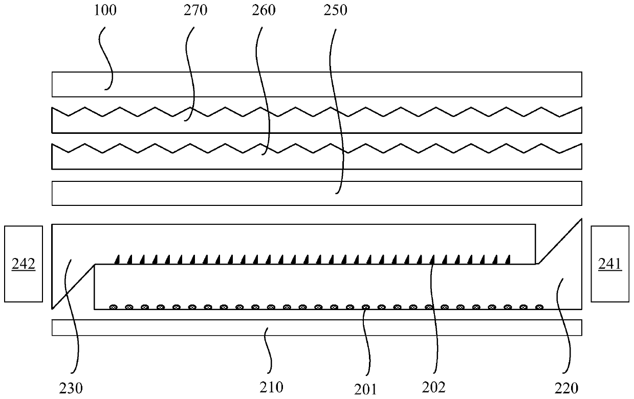
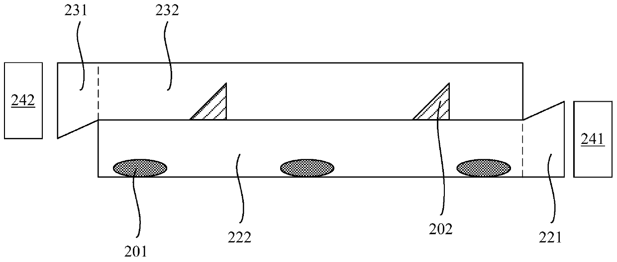
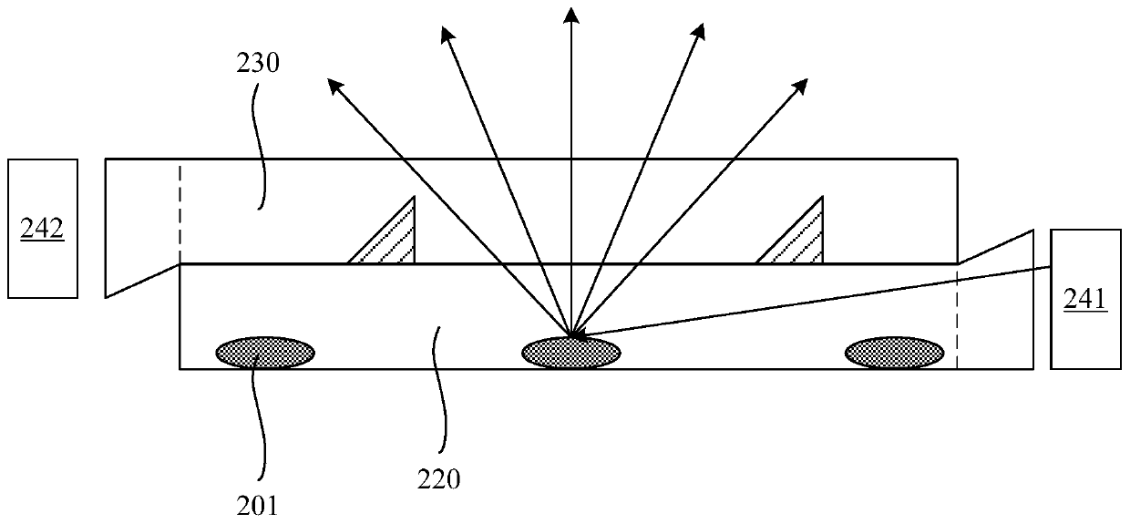
[0028] figure 1 shows a schematic structural diagram of a display device according to an embodiment of the present invention, figure 2 show figure 1 The enlarged structural diagram of the backlight module in the middle part, such as figure 1 figure 2 As shown, the display device of the embodiment of the present invention includes a display panel 100 an...
PUM
 Abstract
Description
Claims
Application Information
 - R&D
- Intellectual Property
- Life Sciences
- Materials
- Tech Scout
- Unparalleled Data Quality
- Higher Quality Content
- 60% Fewer Hallucinations
Browse by: Latest US Patents, China's latest patents, Technical Efficacy Thesaurus, Application Domain, Technology Topic, Popular Technical Reports.
© 2025 PatSnap. All rights reserved.Legal|Privacy policy|Modern Slavery Act Transparency Statement|Sitemap|About US| Contact US: help@patsnap.com