Cross-machine-room data synchronization method and system

A data synchronization, cross-machine room technology, applied in the field of distributed systems, can solve the problems of code redundancy, inseparable from channel traffic message middleware dependence, low data synchronization efficiency, etc., to achieve strong scalability and reduce the number of code repetitions. Effect

Active Publication Date: 2019-10-08
FOCUS TECH
View PDF5 Cites 6 Cited by
  • Summary
  • Abstract
  • Description
  • Claims
  • Application Information

AI Technical Summary

Problems solved by technology

To ensure availability, large-scale websites will adopt a multi-active deployment architecture in different places. Therefore, configuration applications also need to be deployed in each computer room. Configuration data is usually stored in a database, and based on the log replay mechanism that comes with the database, the data is synchronized to all computer rooms. , but because this data synchronization mode adopts a single channel, that is, different computer room databases adopt a direct connection mode, which is limited by the traffic and transmission speed of the network channel, the transmission of large amounts of data will undoubtedly lead to congestion, and the synchronization performance will drop sharply , data synchronization is inefficient
[0003] Secondly, the message middleware technology solves the dilemma that data synchronization in a distributed environment relies on a single channel, and achieves the purpose of concurrently processing different message delivery. However, it brings a new problem, that is, it is necessary to compile different call messages for different business operations. As the business volume increases, more and more call codes are compiled for the

Method used


Image

  • Cross-machine-room data synchronization method and system
  • Cross-machine-room data synchronization method and system
  • Cross-machine-room data synchronization method and system

Examples


Example Embodiment

[0036] The present invention will be further described below in conjunction with the accompanying drawings and exemplary embodiments:

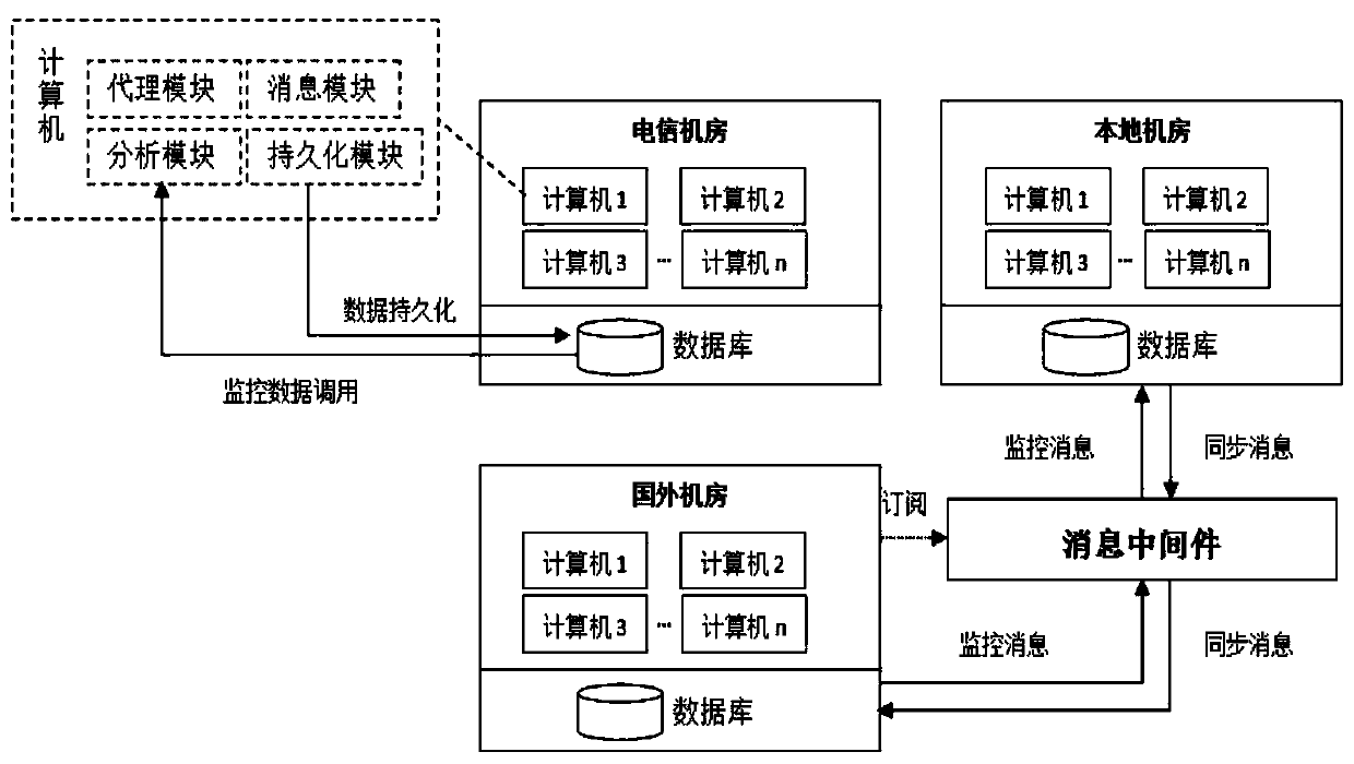
[0037] In the embodiment of the present invention, in a cross-computer room environment, the computer room where the data change action occurs automatically becomes the producer (hereinafter referred to as: production room), and other computer rooms automatically become consumers (hereinafter referred to as the consumer computer room);

[0038] figure 1 This is a schematic diagram of a data synchronization structure across computer rooms in an embodiment of the present invention, including a telecommunications computer room, a local computer room, and a foreign computer room. In the embodiment of the present invention, the local computer room is the production computer room by default, and the telecommunications computer room and the foreign computer room are consumer computer rooms. Foreign computer rooms subscribe to the synchronization service of...


PUM


Abstract

The invention discloses a cross-machine-room data synchronization method and system. The method is characterized in that an agent object is generated to intercept a data change action so as to capturethe data change action of a producer, the data change action is packaged into a synchronous message, the synchronous message is transmitted to a consumer who subscribes the data change action throughmessage middleware, the consumer can be triggered to generate the same data change action as the producer through message unpacking, and cross-machine-room data synchronization is completed; and in the synchronous execution process, the synchronous monitoring table is used for recording the data synchronization completion condition of each machine room in real time. The technical effects of effectively reducing the number of times of code repeated compilation in the data synchronization process and being extremely high in expansibility are achieved. In the synchronous execution process, the data synchronization completion condition of each machine room is recorded in real time through a persistent synchronous monitoring table, meanwhile, the data synchronization process can be dynamicallymonitored in real time, and timely intervention is achieved when a synchronization problem occurs.

Description

technical field [0001] The invention relates to the field of distributed systems, in particular to a data synchronization method and system across computer rooms. Background technique [0002] With the maturity and popularity of the microservice architecture, the configuration center is one of the core middleware supporting the architecture. The configuration center is generally a CS architecture. It consists of application and management application, both of which are independently deployed applications. The configuration application is responsible for processing configuration read and write requests from the client and management application; the management application provides web operation pages and sends requests to the configuration application in the background to complete configuration management. To ensure availability, large-scale websites will adopt a multi-active deployment architecture in different places. Therefore, configuration applications also need to be de...

Claims


Application Information

Patent Timeline
IPC IPC(8): G06F16/27
CPCG06F16/275
Inventor 王亚军
Owner FOCUS TECH
Why Eureka
Try Eureka