SPDMD-based power system oscillation mode and modal identification method
An oscillation mode and power system technology, applied in the field of power systems, can solve problems that affect calculation efficiency, cannot analyze system oscillation characteristics, and cannot consider system integrity, so as to improve efficiency, improve real-time monitoring capabilities, and improve dynamic stability. Effect
- Summary
- Abstract
- Description
- Claims
- Application Information
AI Technical Summary
Problems solved by technology
Method used
Image
Examples
Embodiment 1
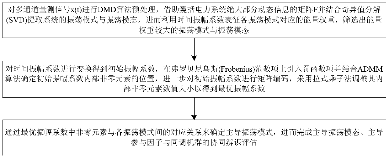
[0058] A power system oscillation mode and mode identification method based on SPDMD, see figure 1 , the method includes the following steps:
[0059] 101: Perform DMD algorithm preprocessing on the multi-channel measurement signal x(t), use the matrix F that includes most of the dynamic information of the power system and introduce SVD to extract the oscillation mode and oscillation mode of the system, and then use the time amplitude coefficient to characterize each The energy weight corresponding to the oscillation mode, and screen out the oscillation mode and oscillation mode with a large energy weight;
[0060] Wherein, the above-mentioned multi-channel measurement signal x(t) is the measurement data collected by all PMUs. For example, one PMU collects the measurement signal of one generator, and the data collected by n PMUs is the wide-area measurement data.
[0061] 102: Transform the matrix composed of the first N-1 columns of measurement data sequences to calculate th...
Embodiment 2
[0066] The scheme in Example 1 will be further introduced in combination with specific calculation formulas and examples, see the description below for details:
[0067] 201: Use the PMU device to obtain multi-channel wide-area measurement data, perform standardized processing on it, and use the DMD algorithm to preprocess the standardized data;
[0068] 1) Standardize the measurement data as follows:
[0069] x i,new =(x i -mean(x i )). / std(x i ) (1)
[0070] where x i is the measurement data of a certain measurement channel, mean and std respectively represent the mean and standard deviation of the data vector. The purpose of standardizing the multi-channel measurement data is to make the measurement data at the same order of magnitude and make them comparable, making it easier to compare data and retain the inherent oscillation information of the measurement data.
[0071] 2) Perform DMD algorithm preprocessing on the standardized measurement data;
[0072] Since th...
Embodiment 3
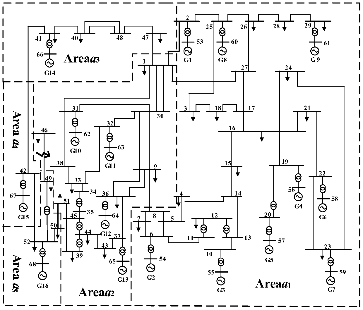
[0204] In the following, in combination with specific examples, aiming at the power system oscillation mode and mode identification method based on the SPDMD algorithm proposed in the embodiment of the present invention, this example takes the IEEE-68 node system as an example for simulation analysis and verification, and the IEEE-68 node system Topology such as figure 2 As shown, see the description below:
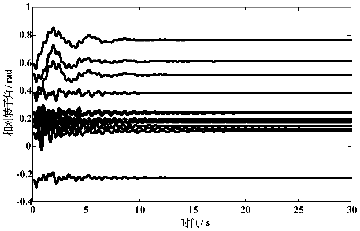
[0205] In this calculation example, a three-phase short-circuit fault is set on the side of branch 46-49 near node 49 at 0.1s, the circuit breaker at node 49 trips at 0.26s, and the circuit breaker at node 46 trips at 0.28s. Taking generator G1 as the reference motor, and the relative rotor power angle and relative rotor angular velocity of other generators relative to the first generator as the signals to be identified, 16 generators generate 15 sets of relative rotor power angle signals and 15 sets of relative rotor power angle signals in total. Angular velocity signa...
PUM
 Abstract
Description
Claims
Application Information
 - R&D
- Intellectual Property
- Life Sciences
- Materials
- Tech Scout
- Unparalleled Data Quality
- Higher Quality Content
- 60% Fewer Hallucinations
Browse by: Latest US Patents, China's latest patents, Technical Efficacy Thesaurus, Application Domain, Technology Topic, Popular Technical Reports.
© 2025 PatSnap. All rights reserved.Legal|Privacy policy|Modern Slavery Act Transparency Statement|Sitemap|About US| Contact US: help@patsnap.com


