Amorphous alloy golf club head and manufacturing method thereof
What is AI technical title?
AI technical title is built by Patsnap AI team. It summarizes the technical point description of the patent document.
A golf club head, amorphous alloy technology, applied in golf balls, golf clubs, sports accessories, etc., can solve the problems of amorphous and crystalline mixtures, etc., to improve the ability to form amorphous, ensure quality, and good energy transfer performance effect
Active Publication Date: 2019-10-11
NANJING YOUTIAN METAL TECH
View PDF8 Cites 0 Cited by
Summary
Abstract
Description
Claims
Application Information
AI Technical Summary
This helps you quickly interpret patents by identifying the three key elements:
Problems solved by technology
Method used
Benefits of technology
Problems solved by technology
It solves the technical problem that the amorphous alloy golf club head made of the existing amorphous alloy easily forms a mixture of amorphous and crystal
Method used
Image
Click on the blue label to locate the original text in one second.
Reading with bidirectional positioning of images and text.
Examples
Embodiment 1
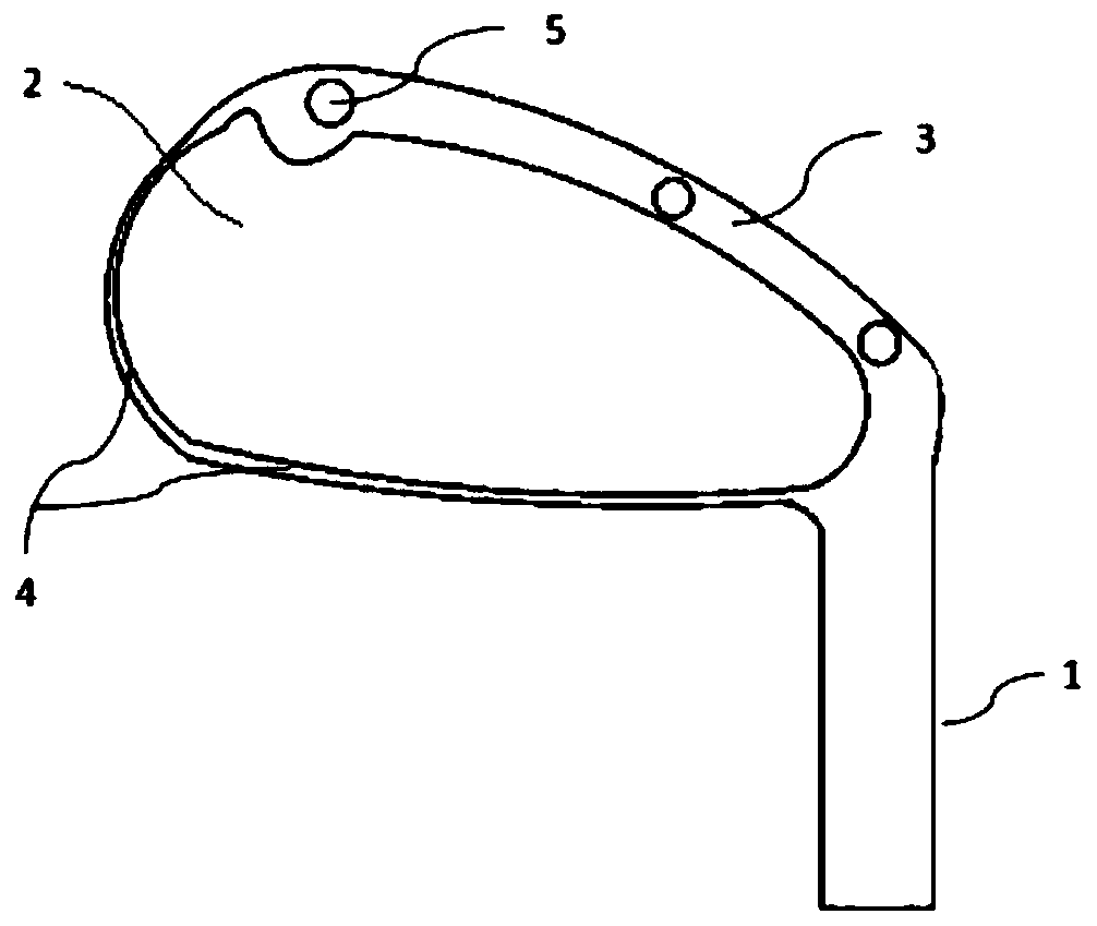
[0067] like Figure 4 As shown, an amorphous alloy golf club head of the present invention is integrally cast from an amorphous metal material, including:
[0068] a neck for coupling with the club;
[0069] a batting panel attached to the bottom of said neck;
[0070] a peripheral wall positioned behind the ball striking panel, the ball striking panel and peripheral wall forming a rear concave cavity;
[0071] The peripheral wall body includes a thin-walled portion enclosing the upper edge and the rear side edge of the ball striking panel, and a section of thick-walled portion enclosing the bottom of the ball striking panel rear;
[0072] A pad, embedded in the thick-walled part, is used to reduce the casting thickness of the thick-walled part; the embedded pad is provided with 3 pillars,
[0073] One end of each pillar is fixedly connected to the block body, and the other end of the pillar has an exposed surface that is not covered by the above-mentioned peripheral wall; ...
Embodiment 2
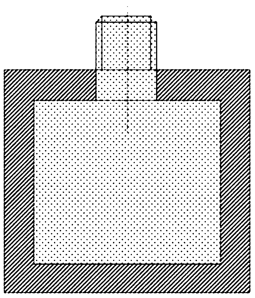
[0075] like image 3 As shown, an amorphous alloy golf club head of the present invention is integrally cast from an amorphous metal material, including:
[0076] a neck for coupling with the club;
[0077] a batting panel attached to the bottom of said neck;
[0078] a peripheral wall positioned behind the ball striking panel, the ball striking panel and peripheral wall forming a rear concave cavity;
[0079] The peripheral wall body includes a thin-walled portion enclosing the upper edge and the rear side edge of the ball striking panel, and a section of thick-walled portion enclosing the bottom of the ball striking panel rear;
[0080] A spacer, embedded in the thick-walled part, is used to reduce the casting thickness of the thick-walled part; the embedded spacer is provided with 3 metal pillars,
[0081] One end of the metal prop is fixedly connected to the spacer body, the other end of the metal prop has a bare section, the outer wall of the bare section is provided w...
PUM
Property
Measurement
Unit
thickness
aaaaa
aaaaa
thickness
aaaaa
aaaaa
thickness
aaaaa
aaaaa
Abstract
The invention discloses an amorphous alloy golf club head and a manufacturing method thereof. A club head is integrally cast from amorphous metal materials, and comprises a neck part used for combining with the golf club, a hitting panel connected with the bottom of the neck part, a peripheral wall body located behind the hitting panel and forming a rear concave cavity with the hitting panel, a cushion block and an adjusting part, wherein the cushion block is arranged in the peripheral wall body in an embedded mode and used for reducing the casting thickness of the peripheral wall body, and aplurality of supporting columns are arranged on the cushion block, one ends of the supporting columns are fixedly connected with the cushion block body, and the other ends of the supporting columns are provided with exposed surfaces or exposed sections which are not covered with the peripheral wall body; and the adjusting part is connected with the supporting columns in a matched mode and used foradjusting the tightness between the cushion block and the peripheral wall body. According to the amorphous alloy golf club head, the golf head is integrally cast by adopting amorphous alloy, and thetechnical problem that the amorphous alloy golf head made of the existing amorphous alloy is very easy to form the mixture of the amorphous and crystal is solved.
Description
technical field [0001] The invention discloses an amorphous alloy golf club head, in particular to an amorphous alloy golf club head made of an amorphous alloy material. Background technique [0002] Golf is a leisure sport with a long history that has evolved through centuries. As an important part of the golf club, the golf club head will deform to a certain extent when the golf ball is hit. In order to increase the speed of the ball when hitting the ball, to fly a long distance, and to prevent the club head from breaking, the material of the club head should have certain strength, toughness and hardness, high modulus of elasticity and low internal friction. [0003] With the continuous improvement of functional requirements, golf club head materials have gradually evolved from the earliest hickory wood and persimmon wood to the commonly used materials such as titanium alloy, stainless steel and aluminum alloy. The striking faces made of titanium alloy, stainless steel a...
Claims
Application Information
Patent Timeline
Application Date:The date an application was filed.
Publication Date:The date a patent or application was officially published.
First Publication Date:The earliest publication date of a patent with the same application number.
Issue Date:Publication date of the patent grant document.
PCT Entry Date:The Entry date of PCT National Phase.
Estimated Expiry Date:The statutory expiry date of a patent right according to the Patent Law, and it is the longest term of protection that the patent right can achieve without the termination of the patent right due to other reasons(Term extension factor has been taken into account ).
Invalid Date:Actual expiry date is based on effective date or publication date of legal transaction data of invalid patent.

