
Composite conductor rail and manufacturing method thereof

A technology of composite conduction and manufacturing methods, which is applied in the field of rail transit, can solve the problems of poor dimensional stability of composite conductive rails, large residual stress at the joint of aluminum rails, increased production costs, etc., and achieve good reliability, simple cross-sectional shape, The effect of convenient processing

Active Publication Date: 2019-10-11
BYD CO LTD
View PDF6 Cites 0 Cited by
  • Summary
  • Abstract
  • Description
  • Claims
  • Application Information

AI Technical Summary

Problems solved by technology

[0003] In the related technology, the composite surface of the C-shaped steel-aluminum composite conductive rail is a curved surface with complex shape, which needs to be embedded into the dimple of the steel belt through the plastic deformation of the aluminum rail for composite. The process is relatively complicated and the production is difficult. After composite, The residual stress of the joint between the aluminum rail and the steel belt is relatively large, which leads to poor dimensional stability of the composite conductor rail, and is accompanied by the phenomenon of cold work hardening, which makes the aluminum rail at the joint become brittle
Therefore, this C-shaped steel-aluminum composite conductor rail generally needs aging treatment to eliminate internal stress and soften the structure, thereby increasing the production cost

Method used

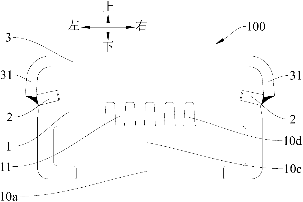
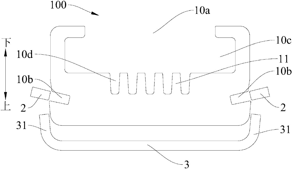
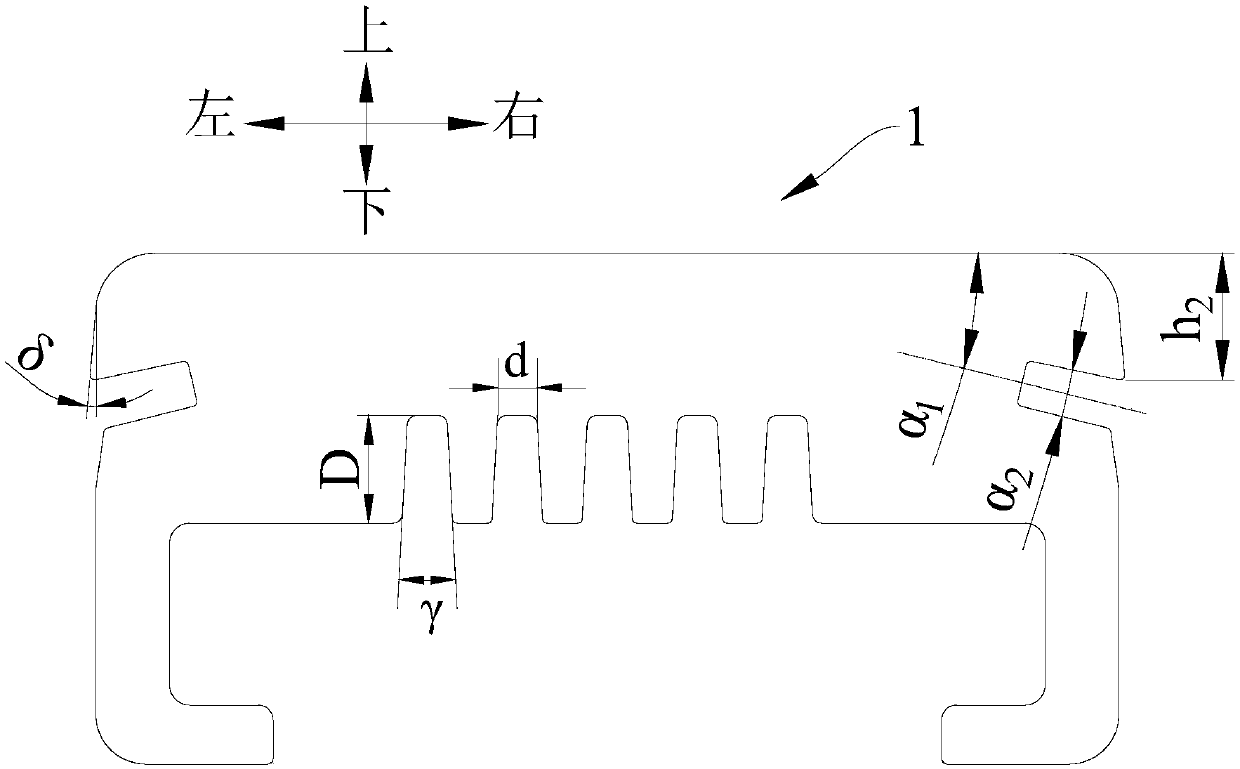

Image

  • Composite conductor rail and manufacturing method thereof
  • Composite conductor rail and manufacturing method thereof
  • Composite conductor rail and manufacturing method thereof

Examples


Embodiment Construction

[0040] Embodiments of the present invention are described in detail below, examples of which are shown in the drawings, wherein the same or similar reference numerals designate the same or similar elements or elements having the same or similar functions throughout. The embodiments described below by referring to the figures are exemplary only for explaining the present invention and should not be construed as limiting the present invention.

[0041] In describing the present invention, it is to be understood that the terms "center", "height", "thickness", "upper", "lower", "left", "right", "vertical", "horizontal", The orientation or positional relationship indicated by "inner", "outer", "axial" and "radial" are based on the orientation or positional relationship shown in the drawings, and are only for the convenience of describing the present invention and simplifying the description, rather than indicating Or imply that the device or element referred to must have a specific...


PUM

PropertyMeasurementUnit
thicknessaaaaaaaaaa
radiusaaaaaaaaaa

Abstract

The invention discloses a composite conductor rail and a manufacturing method thereof. The composite conductor rail includes an aluminum rail, two first steel strips, and a second steel strip. The aluminum rail is formed in a C shape, so that one side of the aluminum rail is formed with an opening, grooves are respectively formed on both opposite sides of the aluminum rail, the grooves are disposed in an inclination manner orienting to a direction close to each other and orienting to the opening away from the aluminum rail, and the grooves are formed as wedge grooves; the two first steel strips are matched in the two grooves in a one to one correspondence manner; and the second steel strip is formed as a C-shaped steel strip, and the second steel strip is provided with two oppositely disposed side edges, the second steel strip is pressed against the other side surface of the aluminum rail, each of the side edges extends toward one side of the aluminum rail to the side wall exceeding one side of the corresponding groove adjacent to the aluminum rail, and the two side edges are respectively welded to the two first steel strips in an overlapping manner. The composite conductor rail ofthe invention is simple in processing process, high in production efficiency, low in cost, and stable in performance.

Description

technical field [0001] The invention relates to the technical field of rail transit, in particular to a composite conductive rail and a manufacturing method thereof. Background technique [0002] For the conductor rails in the current receiving system of straddle-type monorail trains and low- and medium-speed maglev trains, they are mainly C-shaped steel-aluminum composite conductor rails and I-shaped steel-aluminum composite conductor rails. Compared with I-shaped steel-aluminum composite conductor rails, C-shaped steel-aluminum composite conductor rails The composite conductor rail is lighter, has better heat dissipation, and higher conductivity, and the interior of the C-shaped steel-aluminum composite conductor rail is less likely to crack. [0003] In the related technology, the composite surface of the C-shaped steel-aluminum composite conductive rail is a curved surface with complex shape, which needs to be embedded into the dimple of the steel belt through the plasti...

Claims


Application Information

Patent Timeline
Patent Type & Authority Applications(China)
IPC IPC(8): B60M1/30B23P15/00
CPCB60M1/302B23P15/00
Inventor 姚强程冲袁清辉
Owner BYD CO LTD
Learn More