
Touch panel capable of reducing Moire effect

A touch panel and effect technology, applied in the input/output process of data processing, instruments, calculations, etc., can solve the problems of reducing the number of nodes, affecting the transmittance, and increasing the production cost, reducing interference fringes and improving identification. The effect of saving the production cost

Inactive Publication Date: 2019-10-11
INTECH ELECTRONICS
View PDF5 Cites 1 Cited by
  • Summary
  • Abstract
  • Description
  • Claims
  • Application Information

AI Technical Summary

Problems solved by technology

[0004] In order to avoid or reduce the occurrence of interference fringes, the line width of the wire can be between 1 micron and 3 microns. Such a fine line width must be produced by a high-resolution glass mask, but the cost of the glass mask Expensive, leading to higher initial development and manufacturing costs
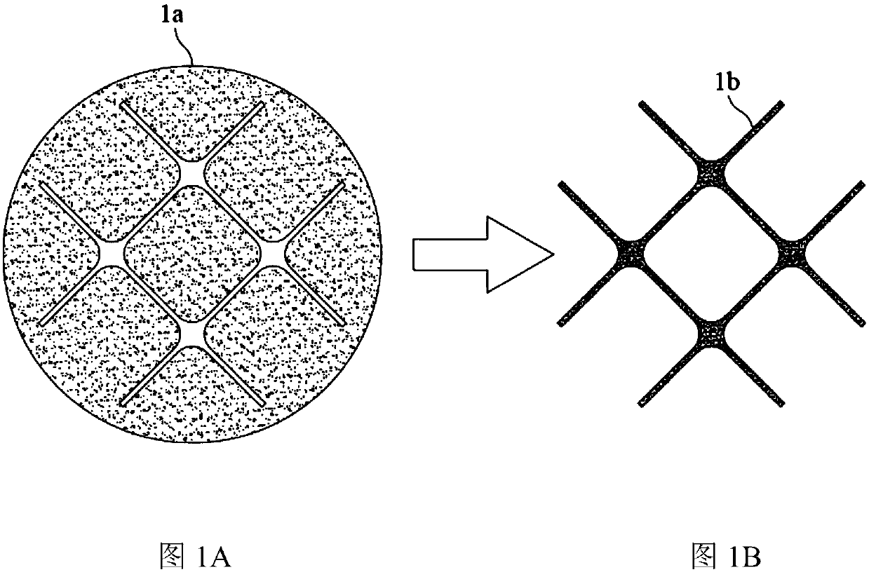
[0005] Therefore, it is possible to pass through the thin-film mask (see Figure 1A ), but the thin film mask 1a has a lower resolution than the glass mask, so compared to the glass mask, there will be a phenomenon of expansion at the intersection of the lines, and the film mask 1a is etched by exposure and development. process, the metal grid 1b made (such as Figure 1B ), the line width is only between 5 and 8 microns, and many nodes N will be formed at the intersections of the lines. And each node is a uniform shape of a positive cross, so when the light reaches the node, it is easy to diffract, which affects the light transmittance and seriously affects the display effect
[0006] Refer to Taiwan Invention Patent Announcement No. I601043 "Touch Panel with Non-Sensing Function Metal Lines", which mainly includes a light-transmitting substrate and two sensing electrodes. The two sensing electrodes face each other across the light-transmitting substrate. It includes metal lines with induction function and metal lines without induction function, and the opposite metal mesh also forms interlaced lines; the purpose of this case is to avoid the diffraction effect, and the technical means used in this case is to use the metal mesh The area of ​​each grid of the grid becomes larger (that is, the grid density becomes larger), and the number of nodes can be reduced. However, the reduction in the number of nodes means that there are fewer locations that emit diffraction effects, but the area of ​​the nodes themselves has not been reduced. , there may still be diffraction effects
[0007] In addition, when the "metal lines with sensing function" and "metal lines without sensing function" are interlaced in this case, although they can form a grid pattern invisible to the naked eye as a whole, the above two are regular grid pattern, so the interlacing is still a regular grid pattern, that is, the interval between the metal lines is fixed, so when it is attached to a display panel of different specifications, it will be compatible with certain specifications of the black matrix ( Black Matrix) and color filter layers have interference fringe phenomenon, so it is necessary to design additional metal grids with different arrangement intervals; but it will bring the problem of high production cost, and there is also the problem of diffraction effect at the nodes to be overcome

Method used


Image

  • Touch panel capable of reducing Moire effect
  • Touch panel capable of reducing Moire effect
  • Touch panel capable of reducing Moire effect

Examples


Embodiment Construction

[0042] The embodiments of the present invention will be described in more detail below in conjunction with icons and component symbols, so that those skilled in the art can implement them after studying this specification.

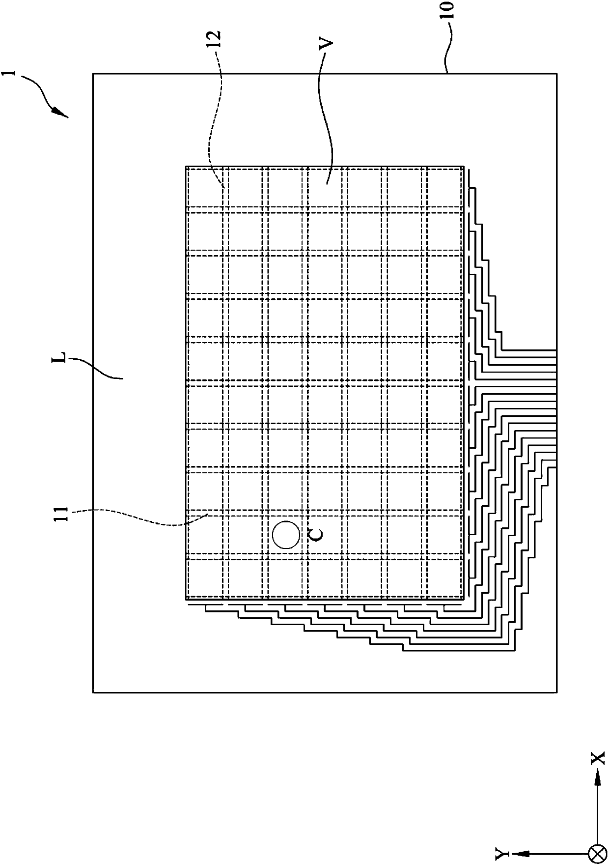
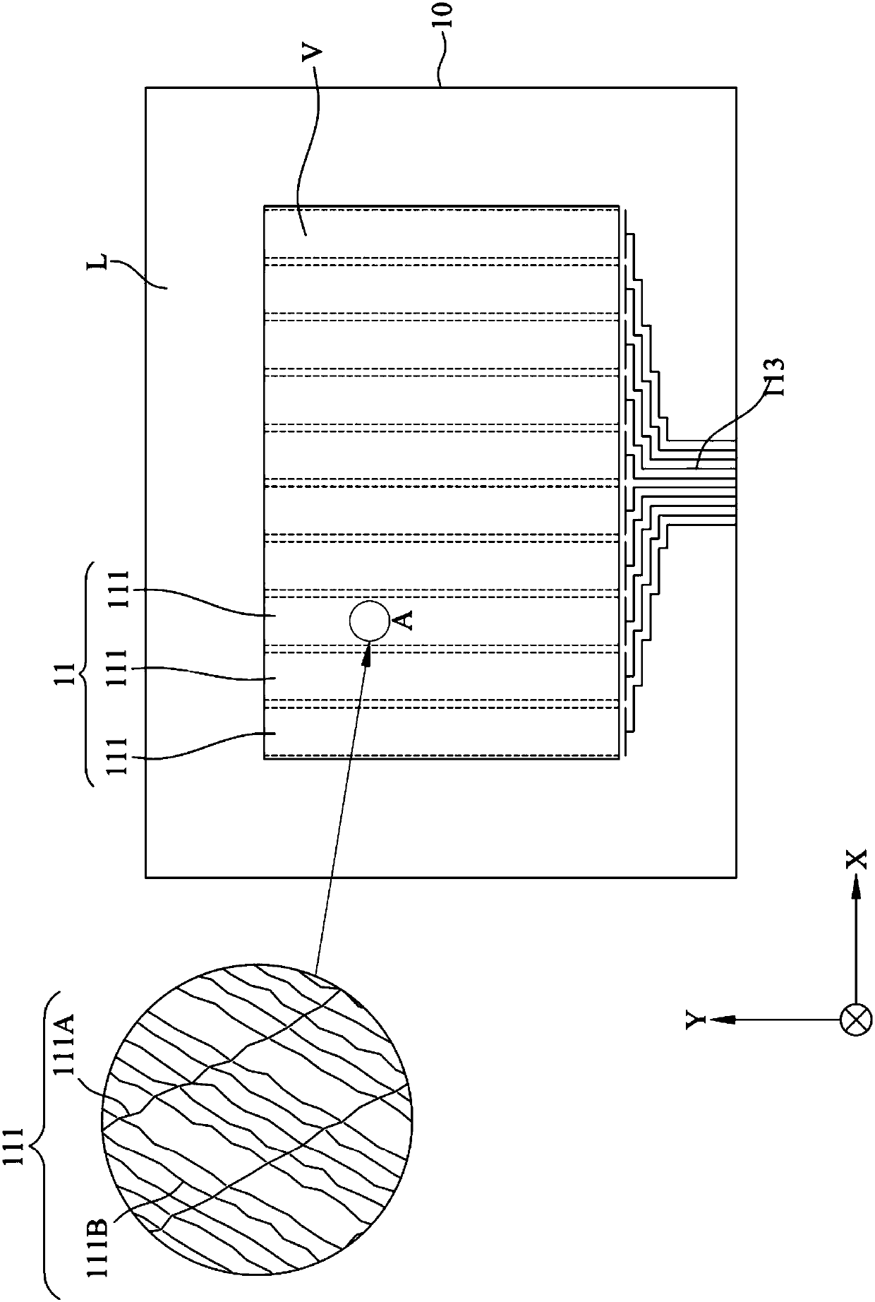
[0043] refer to figure 2 , figure 2 It is a schematic diagram of a touch panel capable of reducing the Murray effect of the present invention. Such as figure 2As shown, the touch panel 1 capable of reducing the Murray effect of the present invention at least includes a light-transmitting substrate 10, a first sensing unit 11, and a second sensing unit 12, wherein the light-transmitting substrate 10 includes a visible touch panel region V and a peripheral circuit region L, wherein the peripheral circuit region L is between the edge of the light-transmissive substrate 10 and the visible touch region V, and the visible touch region V is the non-contact area of ​​the light-transmissive substrate 10 Edge area, the peripheral circuit area L is the edge are...


PUM


Abstract

The invention discloses a touch panel capable of reducing a Moire effect. The touch panel mainly comprises a light-transmitting substrate and two induction electrodes. The two induction electrodes areopposite to each other across the light-transmitting substrate. The metal grids of the two induction electrodes respectively comprise metal lines without an induction function. The included angle between the metal lines with the induction function is determined in a random number mode under a specific condition. Therefore, the area of the node is reduced. In addition, the metal grids of the two opposite induction electrodes and the metal lines without the induction function can be interlaced with each other to form an interlaced pattern composed of irregular shapes, and therefore the purposethat interference fringes cannot be generated when the metal grids of the two opposite induction electrodes and the metal lines without the induction function are used together with display panels ofvarious mainstream sizes is achieved.

Description

technical field [0001] A touch panel that can reduce the Murray effect, especially a touch panel that can effectively reduce the generation of interference fringes while improving the recognition of touch signals. A glass mask must be used to effectively save production costs, especially when used with display panels of various mainstream sizes, no interference fringes will be produced. Background technique [0002] When the metal grid of the touch panel is attached to the display panel, so-called interference patterns (Moire) are likely to occur, which affects the display quality of the image. The generation of interference fringes is due to the interaction of several factors affecting the light transmittance, such as the shape and arrangement of the metal grid pattern and the line width of the metal grid. When adjacent fringe patterns are regularly arranged with each other, optical interference fringes will be generated, in order to effectively prevent optical phenomena s...

Claims


Application Information

Patent Timeline
Patent Type & Authority Applications(China)
IPC IPC(8): G06F3/041
CPCG06F3/0412G06F2203/04103
Inventor 黄耀贤朱唐墨赖世杰林世典江雅琦林嘉铃
Owner INTECH ELECTRONICS
Learn More