Calibration device and calibration method for joint calibration of laser radar and camera

A lidar and joint calibration technology, applied in image analysis, instruments, calculations, etc., can solve the problems that the calibration device cannot meet the requirements at the same time, the calibration requirements of the lidar and the camera are large and the error is large, and the calibration device and the calibration method are not unified.

Active Publication Date: 2019-10-11
TIANJIN UNIV
View PDF16 Cites 15 Cited by
  • Summary
  • Abstract
  • Description
  • Claims
  • Application Information

AI Technical Summary

Problems solved by technology

[0004] The purpose of the present invention is to overcome the deficiencies in the prior art, provide a calibration device and its calibration method for the joint calibration of laser radar and camera, and solve the problem that the current calibration device and calibration method are not uniform, have poor adaptability, and the calibration device cannot simultaneously The problem of meeting the calibration requirements of lidar and camera with large errors

Method used


Image

  • Calibration device and calibration method for joint calibration of laser radar and camera
  • Calibration device and calibration method for joint calibration of laser radar and camera
  • Calibration device and calibration method for joint calibration of laser radar and camera

Examples


Embodiment Construction

[0047] The present invention will be described in further detail below in conjunction with the accompanying drawings and specific embodiments. It should be understood that the specific embodiments described here are only used to explain the present invention, not to limit the present invention.

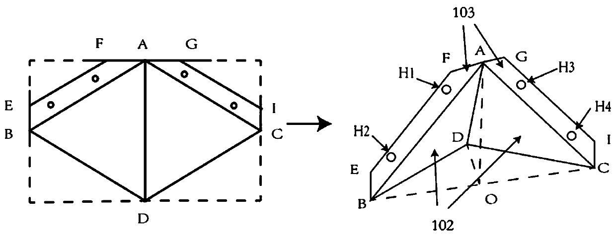
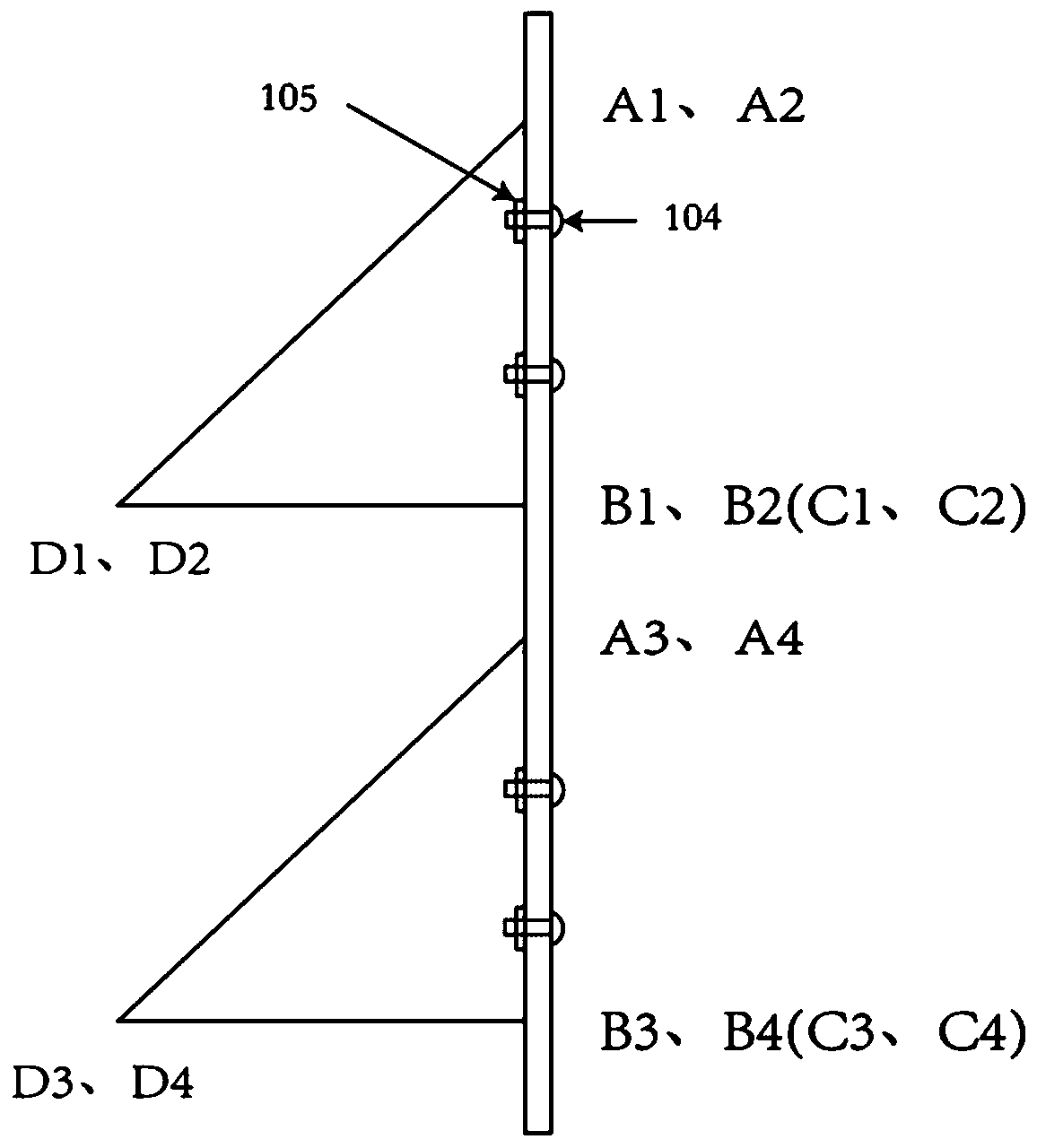
[0048] The present invention is a calibration device and calibration method for joint calibration of laser radar and camera. The calibration device includes a calibration plate, a hollow tetrahedron baffle and a bracket that simultaneously have depth information and corner point information. The calibration method uses " Fitting interpolation method" is a calibration method to find feature point pairs for joint calibration of lidar and camera.

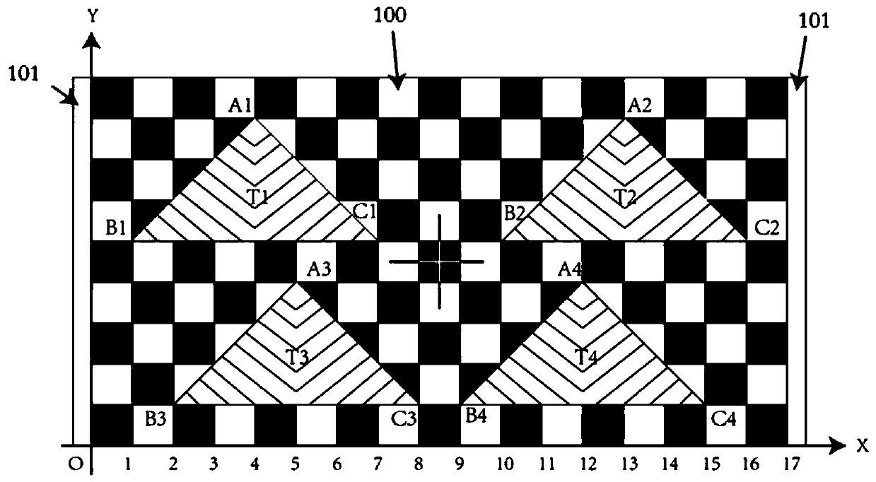
[0049] Among them, the calibration plate in the calibration device is a rectangular plate with an aspect ratio of 1:2, such as figure 1 As shown, there is a cross mark in the center of the calibration board, and a square with side length L is...


PUM


Abstract

The invention discloses a calibration device and a calibration method for joint calibration of a laser radar and a camera. The calibration device is composed of a calibration plate, a hollow tetrahedron baffle and a support. The calibration plate is a rectangular plate provided with a cross mark at the geometric center, and the length-width-height ratio is 1: 1:2 A square with the side length ofL is generated with the cross as the center is formed. 9 * 17 black-white square grids are generated through expansion with the square as the symmetric center. Four isosceles right triangles are arranged at specific positions and hollowed out, a specific hollow tetrahedron baffle is arranged behind a cavity, the bottom of the tetrahedron is matched with the cavity, so that the front-view calibration plate is free of the cavity, and L/2 width vacancies are formed in the two sides of the calibration plate and fixed through a specific support. The calibration method comprises the following steps:calculating coordinates of feature points in a laser radar coordinate system and coordinates of camera pixel coordinate systems according to a fitting interpolation method provided by the invention by using a laser radar detection and camera shooting calibration device, obtaining enough feature point pairs, and substituting the feature point pairs into a coordinate conversion formula to obtain arelative position relationship between the two coordinate systems.

Description

technical field [0001] The invention relates to the fields of laser radar data processing, image data processing and multi-sensor data fusion, and in particular to a calibration device and a calibration method for joint calibration of laser radar and camera. Background technique [0002] At present, the joint application of lidar and camera is becoming more and more extensive. The premise of data fusion between the two is joint calibration, that is, to obtain the relationship between the lidar coordinate system and the camera pixel coordinate system. The feature point method is the most commonly used and simple calibration method. The calibration error mainly comes from the determination of the feature point coordinates of the feature point pairs in the lidar coordinate system and the image pixel coordinate system respectively, which is mainly related to the design of the calibration plate and the corresponding calibration method. , so the structural design of the calibratio...

Claims


Application Information

Patent Timeline
Patent Type & Authority Applications(China)
IPC IPC(8): G06T7/80G01S7/497
CPCG06T7/80G01S7/497
Inventor 蔡怀宇庞伟凇陈晓冬汪毅卓励然
Owner TIANJIN UNIV
Why Eureka
Try Eureka