Systems and methods for compression of three dimensional depth sensing
A depth and depth map technology, applied in the field of compressed 3D depth sensing, can solve the problems of resource occupation and time spent on 3D depth map.
- Summary
- Abstract
- Description
- Claims
- Application Information
AI Technical Summary
Problems solved by technology
Method used
Image
Examples
Embodiment approach 1
[0046] Implementation 1: Combining 2D Image Segmentation with 3D Depth Sensing
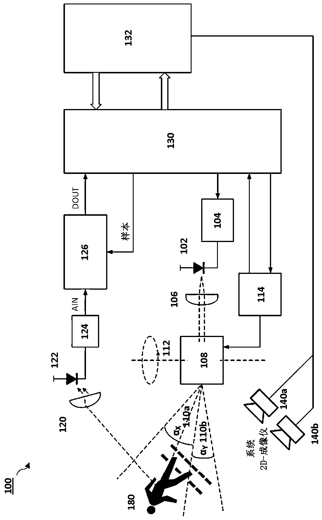
[0047] Aspects of the embodiments relate to systems and methods for utilizing two-dimensional (2D) image data to increase sensing efficiency for acquiring three-dimensional (3D) depth points. In implementations, segmentation can be used to identify regions of interest (ROIs) from our target 2D scene, to obtain depth information or to reduce 3D scans of certain areas.
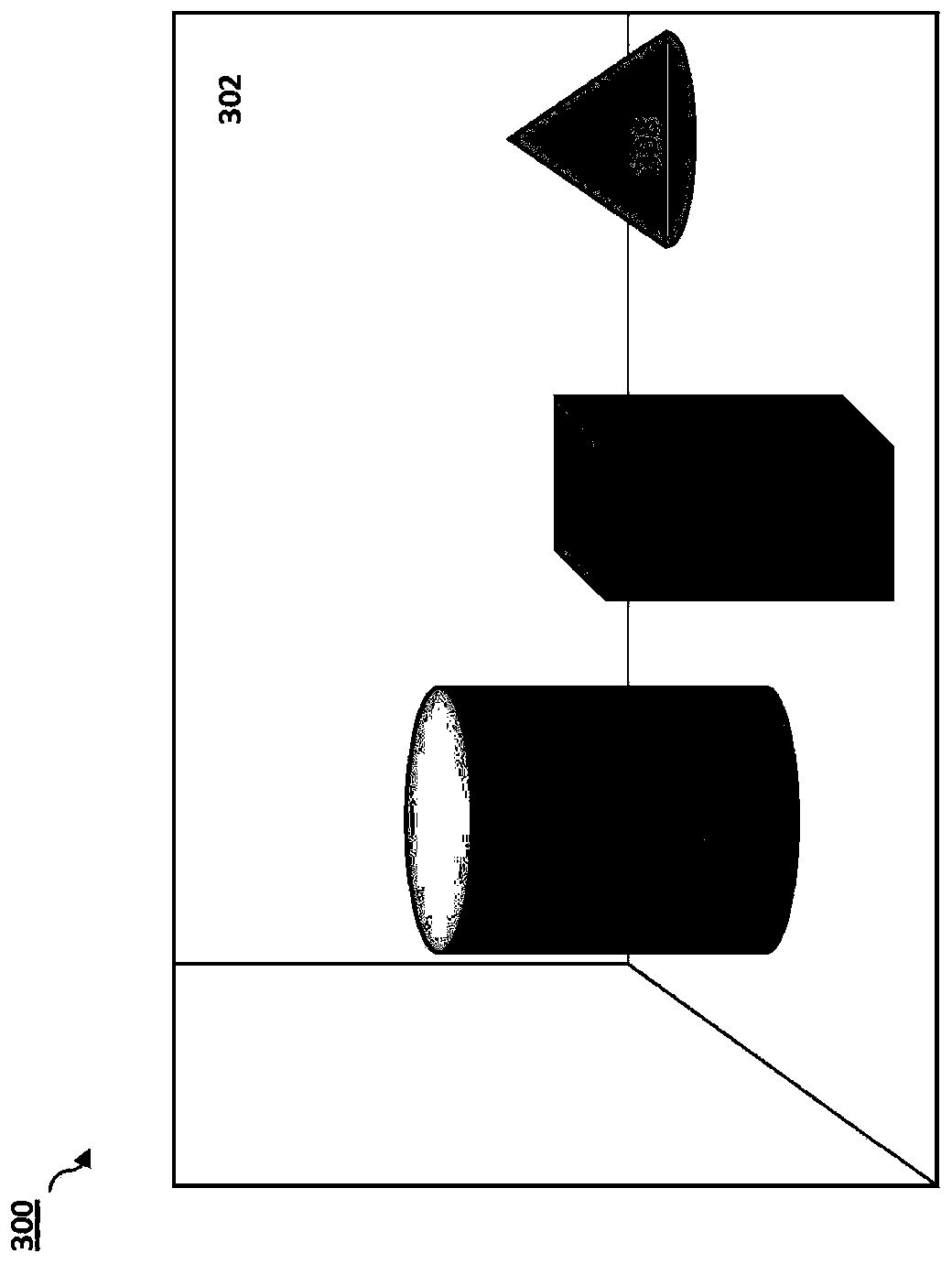
[0048] Figure 3A is a schematic illustration of an image 300 captured by a 2D imaging device according to an embodiment of the disclosure. In image 300, four "objects" are identified: wall 302, cylinder 304, cuboid 306, and cone 308. Image 300 may be captured by a conventional 2D imaging device, such as 2D imaging device 140a or 140b. Figure 3B is a schematic illustration of a segmented 2D image 350 according to an embodiment of the disclosure. After segmentation (or not identified as a target region), wall 352 is shown with...
Embodiment approach 2
[0072] Embodiment 2: Multi-resolution imaging for compressed 3D depth sensing
[0073] Thoroughly scanning the entire image with an active laser takes time and power. Usually scenes are sparse, meaning that most of the information is redundant, especially for pixels that are adjacent to each other, i.e. neighboring pixels. In an embodiment, the scene may be scanned with a depth sensor using a coarse spatial resolution. Depth information can be extracted, as well as the "depth complexity" of each pixel. The region covered by each pixel can be revisited using a finer resolution, depending on the pixel's "depth complexity" (indicating how much 'depth' is involved) and the region's correlation (e.g. based on any one or a combination of prior knowledge of features of a scene or object). Additional factors include the results of previous segmentation of 2D images of the scene, changes observed in 2D images from previous snapshots of the same scene, and / or specific applications (e...
Embodiment approach 3
[0082] Implementation 3: Applying super-resolution to 3D sensing
[0083]In 3D sensing, the pixel resolution may be too coarse due to the area illuminated by the laser beam. The area depends on the system (e.g. collimator), but also on the scene (the same beam covers less area for closer objects than for distant objects). Since some regions are broad and poorly defined (often following a Gaussian illumination pattern), relative overlap between adjacent regions is expected. Higher overlaps can be used to obtain higher resolution images with super-resolution techniques.
[0084] When a pixel is illuminated (and then receives reflected light from) the light distribution from the received reflected light signal is not completely uniform. The overlap between nearby pixels can allow higher resolution depth information to be inferred.
[0085] Figure 11 Three depth signals representing adjacent pixel values are shown according to an embodiment of the disclosure. Finer resolut...
PUM
 Abstract
Description
Claims
Application Information
 - R&D
- Intellectual Property
- Life Sciences
- Materials
- Tech Scout
- Unparalleled Data Quality
- Higher Quality Content
- 60% Fewer Hallucinations
Browse by: Latest US Patents, China's latest patents, Technical Efficacy Thesaurus, Application Domain, Technology Topic, Popular Technical Reports.
© 2025 PatSnap. All rights reserved.Legal|Privacy policy|Modern Slavery Act Transparency Statement|Sitemap|About US| Contact US: help@patsnap.com


