Automatic welding device for tank body

An automatic welding and tank technology, applied in auxiliary devices, welding equipment, welding equipment, etc., can solve the problems of low welding efficiency, high labor cost, and uneven quality of tank welds, so as to ensure the rotation performance and high welding efficiency , good welding quality

Active Publication Date: 2019-10-15
山东华明博奥环保科技有限公司
View PDF7 Cites 0 Cited by
  • Summary
  • Abstract
  • Description
  • Claims
  • Application Information

AI Technical Summary

Problems solved by technology

Due to the human intervention in the manual welding process, the quality of the tank welds varies.
Moreover, the welding efficiency is low and the labor cost is high

Method used


Image

  • Automatic welding device for tank body
  • Automatic welding device for tank body
  • Automatic welding device for tank body

Examples


Embodiment Construction

[0028] In order to clearly illustrate the technical features of the present solution, the present invention will be described in detail below through specific implementation methods and in conjunction with the accompanying drawings. It should be noted that components illustrated in the figures are not necessarily drawn to scale. Descriptions of well-known components and techniques are omitted herein to avoid unnecessarily limiting the present invention.

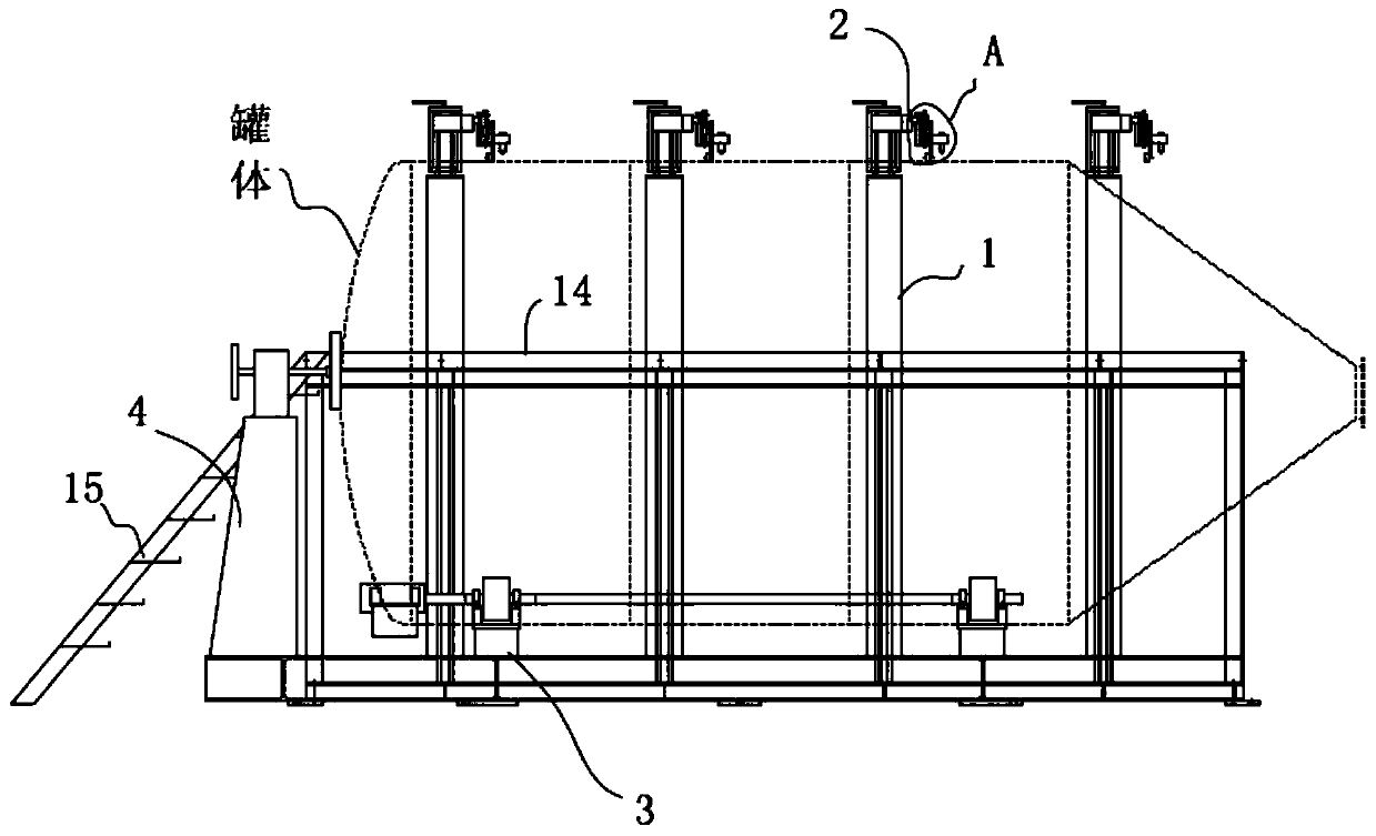
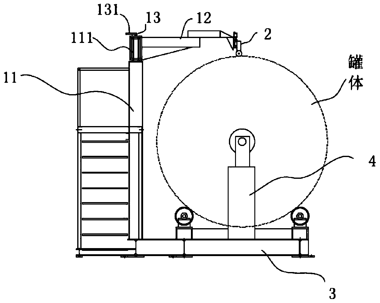
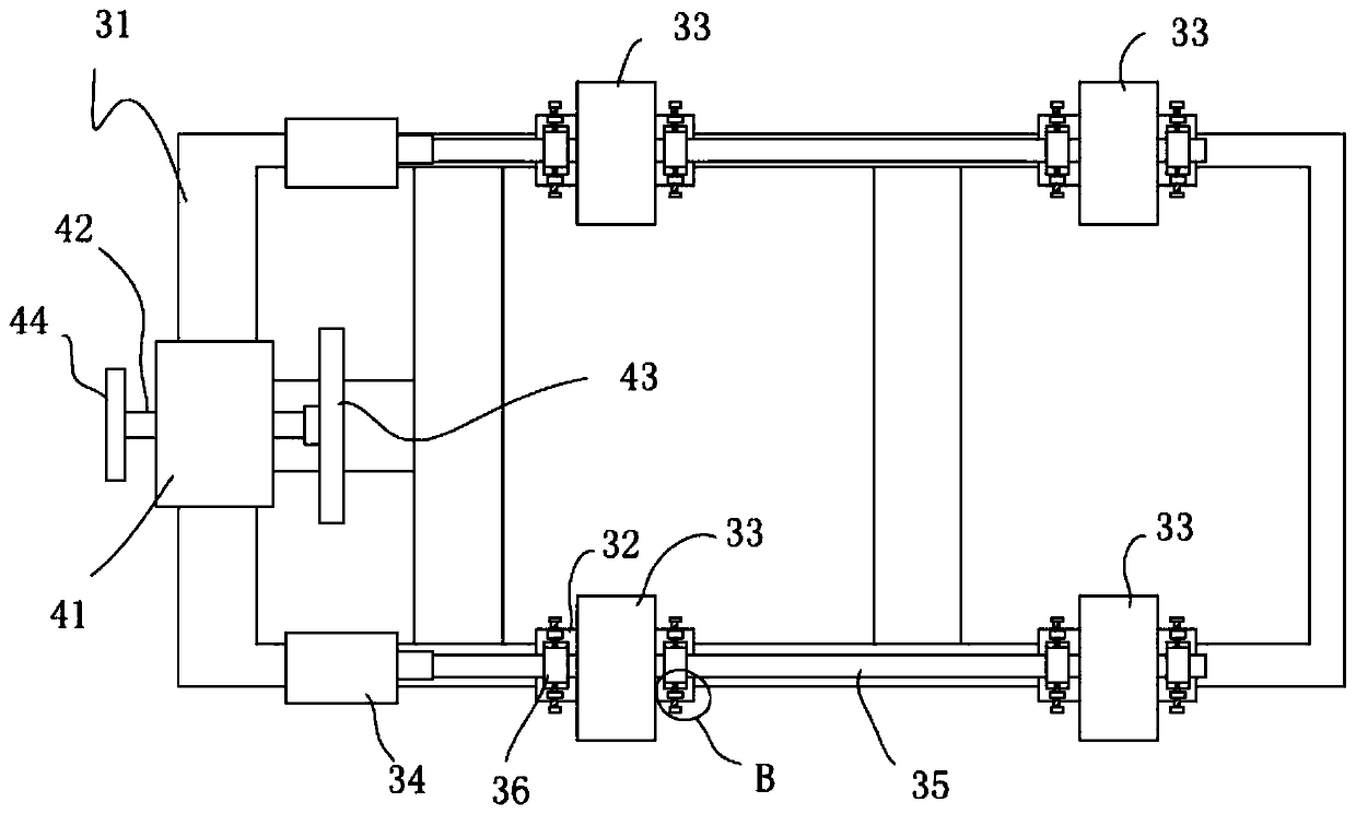
[0029] like Figures 1 to 5 As shown, an automatic tank welding device includes a frame mechanism 1 , a welding cam mechanism 2 , a drive chassis mechanism 3 and a top cone mechanism 4 . The driving chassis mechanism 3 is arranged at the outer lower end of the frame mechanism 1 for carrying and rotatingly driving the welded tank body; the top cone mechanism 4 is arranged at one end of the driving chassis mechanism 3 for the end of the tank body during welding and rotating. Positioning; the welding profiling mechanism 2 is a...


PUM


Abstract

The invention aims at providing an automatic welding device for a tank body, for achieving the purpose of rotary welding for the tank body. The automatic welding device for the tank body comprises a frame body mechanism, a welding profile-modelling mechanism, a drive chassis mechanism and a tip cone mechanism. The drive chassis mechanism is arranged at the lower end of the outer side of the framebody mechanism, and used for bearing and rotationally driving the welded tank body; the tip cone mechanism is arranged at one end of the drive chassis mechanism, and used for locating an end part in awelding rotation process for the tank body; and the welding profile-modelling mechanism is arranged above the frame body mechanism, and used for abutting against the upper end of the welded tank body, and welding a welding joint of the tank body.

Description

technical field [0001] The invention relates to the technical field of tank body rotation welding, in particular to an automatic tank body welding device. Background technique [0002] In the prior art, the welding of the tank body is mostly completed by manual welding. Due to the large diameter of the tank body, welders often need to step on ladders for welding. Due to the many human interference factors in the manual welding process, the quality of the tank welds varies. Moreover, the welding efficiency is low and the labor cost is high. Contents of the invention [0003] The object of the present invention is to provide an automatic tank body welding device, which is used to solve the technical problem of rotary welding of tank bodies. [0004] The technical scheme that the present invention solves its technical problem to take is: [0005] An automatic tank body welding device, comprising a frame body mechanism, a welding profiling mechanism and a driving chassis m...

Claims


Application Information

Patent Timeline
IPC IPC(8): B23K31/02B23K37/053
CPCB23K31/02B23K37/053
Inventor 刘万水陈峰燕方亮杨威
Owner 山东华明博奥环保科技有限公司
Why Eureka
Try Eureka