
Automatic feeding and discharging machine for punching

A technology of automatic loading and unloading and racking, applied in metal processing and other directions, can solve the problems of product wrinkling, inconvenient operation, safety risks, and safety risks.

Pending Publication Date: 2019-10-15
XIAMEN HONGXIN ELECTRON TECH +1
View PDF0 Cites 2 Cited by
  • Summary
  • Abstract
  • Description
  • Claims
  • Application Information

AI Technical Summary

Problems solved by technology

[0002] Before the production of printed circuit boards, the unit products are spliced ​​and designed into a whole board and then processed and manufactured. When the production process reaches the later stage of the forming process, the unit products are processed and separated from the whole board by punching. At present , the processing method is basically to manually operate the punching machine to complete the punching process of the product, and manually complete the loading and unloading operation, especially when the flexible printed circuit board is manually loaded and unloaded, it is easy to cause product wrinkles and other poor quality, and manual operation of the punching machine , there is a safety risk, and in order to realize intelligent manufacturing, it is necessary to realize the automation of punching process
[0003] In view of this, the designer has made in-depth ideas on the many shortcomings and inconveniences caused by the imperfection of the existing punch press structure design, inconvenient operation and safety risks, and actively researched and improved the trial production to develop and design the present invention.

Method used


Image

  • Automatic feeding and discharging machine for punching
  • Automatic feeding and discharging machine for punching
  • Automatic feeding and discharging machine for punching

Examples


Embodiment Construction

[0049] In order to further explain the technical solution of the present invention, the present invention will be described in detail below through specific examples.

[0050] In describing the present invention, it should be understood that the terms "center", "longitudinal", "transverse", "upper", "lower", "front", "rear", "left", "right", " Vertical", "horizontal", "top", "bottom", "inner", "outer" and other indication orientations or positional relationships are based on the orientations or positional relationships shown in the drawings, and are only for the convenience of describing the present invention and simplifying Describes, but does not indicate or imply that the device or element referred to must have a specific orientation, be constructed in a specific orientation, and operate in a specific orientation, and therefore should not be construed as limiting the invention. In the description of the present invention, unless otherwise specified, "plurality" means two or...


PUM


Abstract

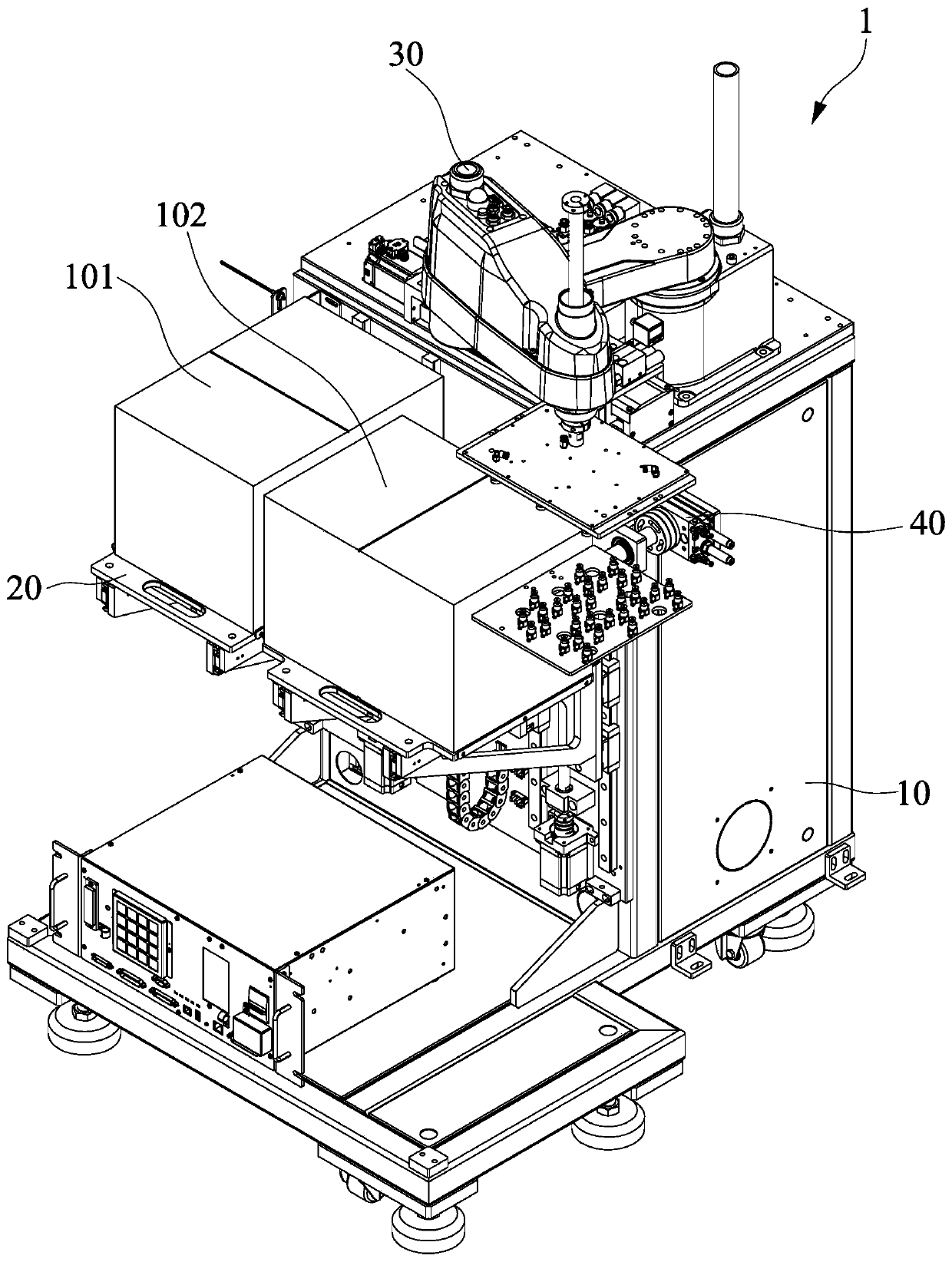
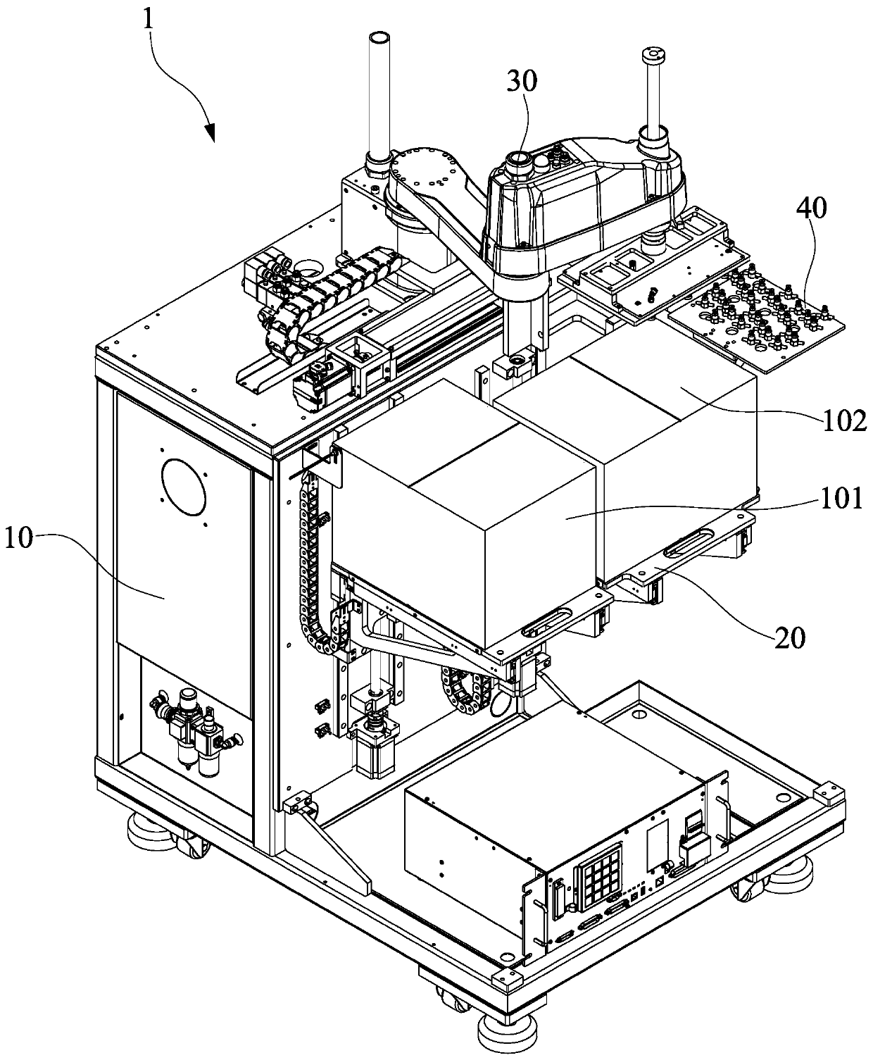
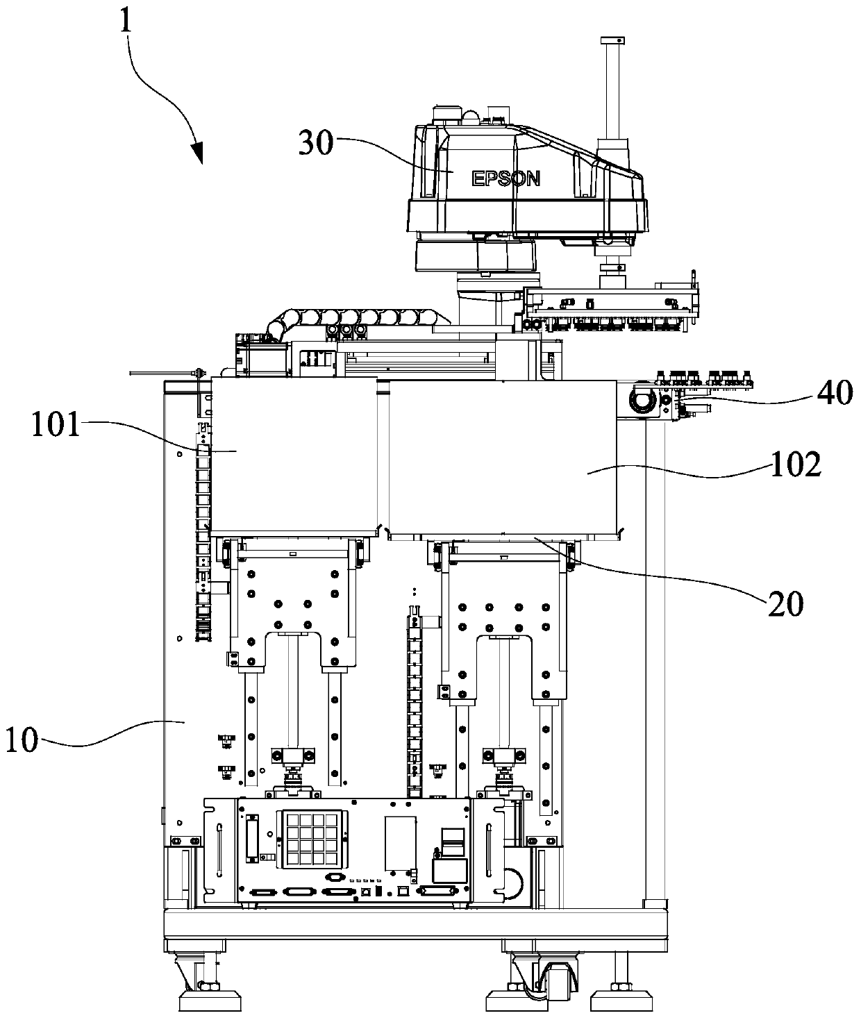
The invention discloses an automatic feeding and discharging machine for punching. The machine comprises a rack, a feeding and discharging mechanism and a mechanical arm mechanism. The feeding and discharging mechanism comprises a feeding assembly and a discharging assembly, the feeding assembly and the discharging assembly are arranged on the front end of the rack side by side in an up and down sliding manner, the mechanical arm mechanism is arranged above the rack, and comprises mechanical arms and a suction cup jig, the mechanical arms are arranged on the rack and can move above the feedingand discharging mechanism, the suction cup jig can be rotatably arranged below the mechanical arms, the suction cup jig is provided with multiple air channels which are independently arranged, duringfeeding, the mechanical arm drives the suction cup jig to suck a product or tray from the position above the feeding assembly, during discharging, the mechanical arms drive the suction cup jig to place the product or tray to the position above the discharging assembly, automation of the punching process of a printed circuit board can be achieved, intelligent manufacturing is achieved, labor forceis saved, production efficiency is improved, the product machining quality is stabilized, and the economic benefits are improved.

Description

technical field [0001] The invention relates to the technical field of production equipment for printed circuit boards, in particular to a punching automatic loading and unloading machine. Background technique [0002] Before the production of printed circuit boards, the unit products are spliced ​​and designed into a whole board and then processed and manufactured. When the production process reaches the later stage of the forming process, the unit products are processed and separated from the whole board by punching. At present , the processing method is basically to manually operate the punching machine to complete the punching process of the product, and manually complete the loading and unloading operation, especially when the flexible printed circuit board is manually loaded and unloaded, it is easy to cause product wrinkles and other poor quality, and manual operation of the punching machine , there are safety risks, and in order to realize intelligent manufacturing, ...

Claims


Application Information

Patent Timeline
IPC IPC(8): B26D7/06B26D7/32B26D7/18
CPCB26D7/06B26D7/32B26D7/18
Inventor 赵继伟包克兵续振林陈明峰朱石宝
Owner XIAMEN HONGXIN ELECTRON TECH
Learn More