Printing head of 3D printer

A 3D printer and print head technology, applied in the field of 3D printing, can solve the problems affecting the printing efficiency of equipment, printing quality problems, manual replacement difficulties, etc., and achieve the effects of stable work, fast printing speed and simple use

Active Publication Date: 2019-10-15
HANGZHOU HIMALAYA INFORMATION TECH
View PDF3 Cites 5 Cited by
  • Summary
  • Abstract
  • Description
  • Claims
  • Application Information

AI Technical Summary

Problems solved by technology

[0004] In actual operation, manual replacement of nozzles is inefficient, which not only indirectly affects the printing efficiency of the equipment, but also easily causes printing quality problems due to the problem of repeated positioning; moreover, the nozzle temperature is high, and manual replacement is difficult

Method used


Image

  • Printing head of 3D printer
  • Printing head of 3D printer
  • Printing head of 3D printer

Examples


Embodiment Construction

[0029] The present invention will be further described below in conjunction with accompanying drawing:

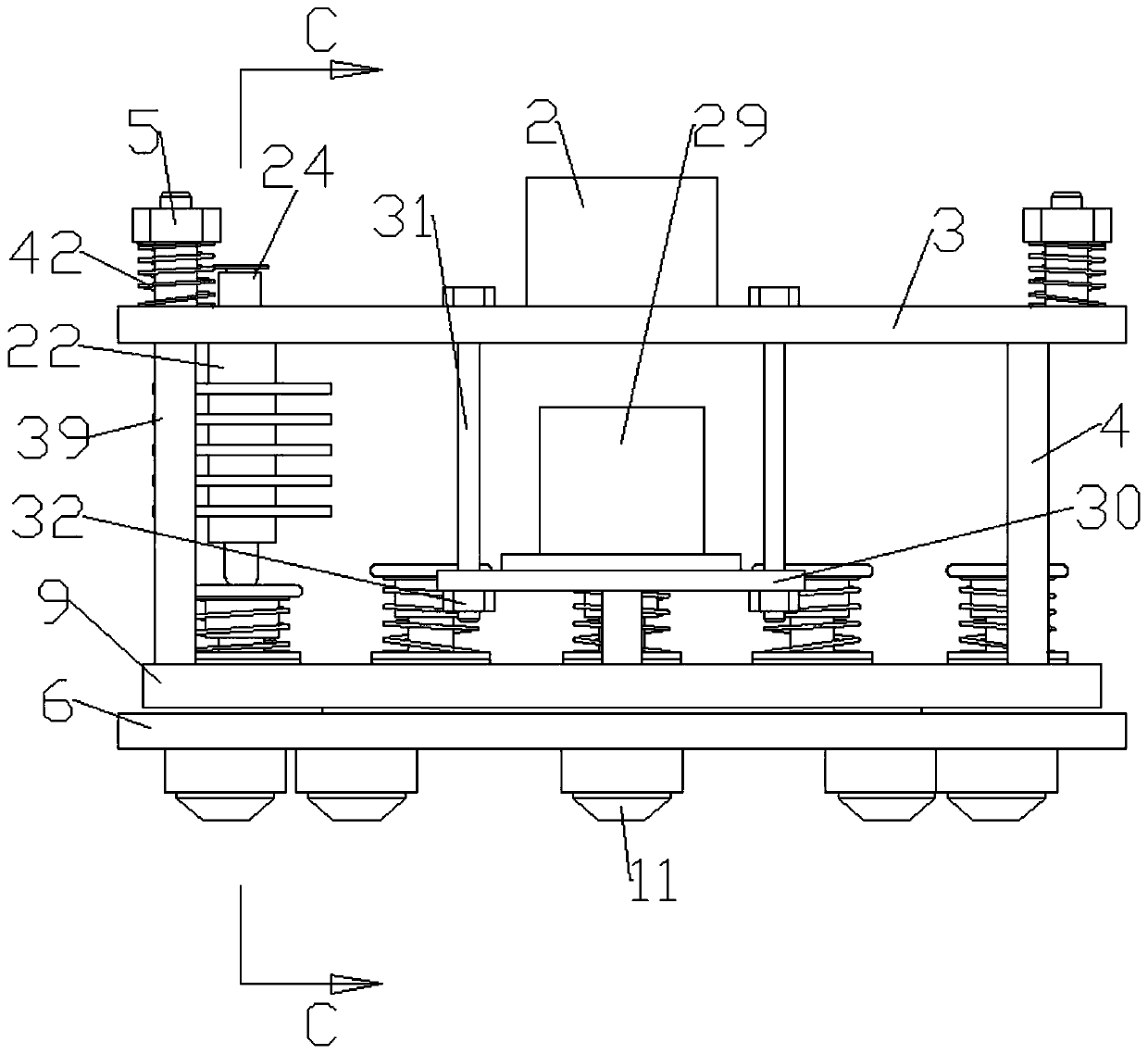
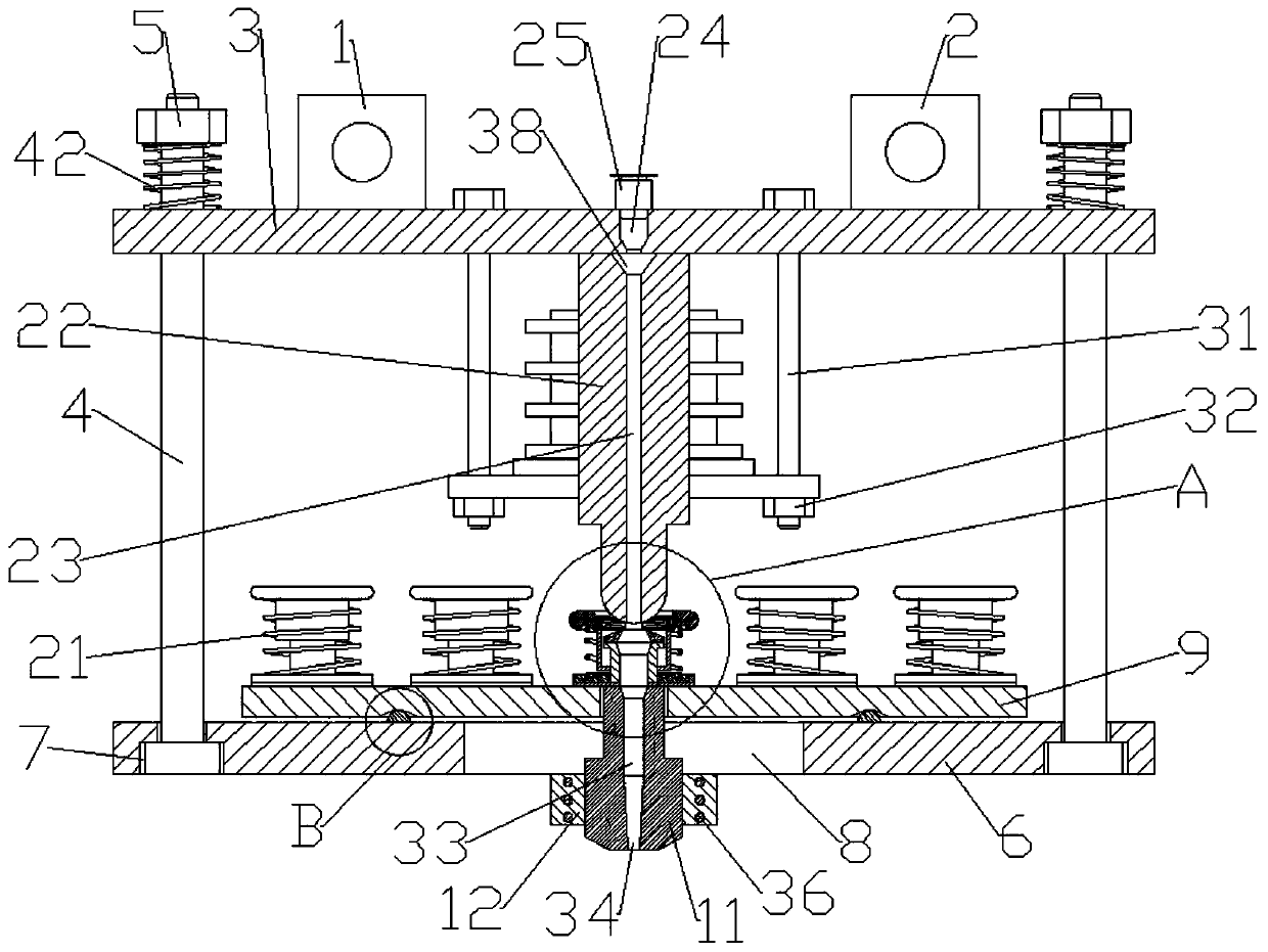
[0030] Refer to attached Figure 1-11 : a print head of a 3D printer in this embodiment, comprising a screw nut 1 connected to the screw rod transmission, the front end of the screw nut 1 is provided with a guide nut 2 parallel to the screw nut 1, the screw nut The lower ends of the nut 1 and the guide nut 2 are fixedly connected with a first connecting plate 3, and several fixing bolts 4 are arranged around the lower end of the first connecting plate 3, and the upper ends of the fixing bolts 4 pass through the first connecting plate 3, so that The outer side of the upper end of the fixing bolt 4 is threadedly connected with the fixing nut 5 located at the upper end of the first connecting plate 3, the outer side of the lower end of the fixing bolt 4 is provided with a second connecting plate 6, and the lower end of the fixing bolt 3 passes through the second Connecting plat...


PUM


Abstract

A printer head of a 3D printer comprises a screw rod nut which is in transmission connection to a screw rod, wherein a first connecting plate is disposed on the lower end of the screw rod nut; a second connecting plate is connected to the lower end of the first connecting plate by a fixation bolt; a rotary hole is formed in the center of the inner side of the second connecting plate; a rotation plate is disposed on the upper end of the second connecting plate; a spray nozzle is in threaded connection to the lower end of the rotation plate; a heating block is disposed on the outer side of the lower end of the spray nozzle; a connecting base is disposed on upper ends of threaded holes; a connecting part is disposed on the inner side in the middle end of the connecting base; a limiting boss is disposed on the outer side of the upper end of the connecting part; a telescopic cylinder is disposed on the outer side of the boss; a seal plate is disposed on the upper end of the telescopic cylinder; a first installation groove is formed in the lower end of the seal plate; a second installation groove is formed in the upper end of the connecting base; a compression spring is disposed on innersides of the first installation groove and the second installation groove; a chock pipe is disposed on the upper end of the left threaded hole; a feeding hole is formed in the inner side of the chockpipe; an installation hole is formed in the upper end of the feeding hole; a pneumatic joint is disposed on the inner side of the upper end of the installation hole; and a feeding hole is disposed onthe lower end of the chock pipe.

Description

technical field [0001] The invention relates to the technical field of 3D printing, in particular to a printing head of a 3D printer. Background technique [0002] With people's continuous exploration and innovation in the field of equipment manufacturing, 3D printing additive manufacturing has received widespread attention and promotion in various manufacturing fields. [0003] The nozzle and the outlet of the 3D printing device are generally threaded, and the viscous material can only be extruded after the nozzle is heated. At present, 3D printing has some problems in the field of industrial printing. For example, when printing complex and large products that cannot be hollowed out, due to the large size of the product and the complex surface structure, if printing with a small nozzle, the efficiency is too low, and the diameter can be used. Large nozzles are used for fast printing; for precision parts or small contours, the use of large nozzles cannot guarantee product q...

Claims


Application Information

Patent Timeline
Patent Type & Authority Applications(China)
IPC IPC(8): B29C64/20B29C64/209B33Y30/00
CPCB33Y30/00B29C64/20B29C64/209
Inventor 祝勇仁赵庆洋范有赖全忠吴俊毛德峰
Owner HANGZHOU HIMALAYA INFORMATION TECH
Why Eureka
Try Eureka