
Floating positioning mechanism

A floating positioning mechanism and floating positioning technology, which is applied in the direction of electric vehicles, electric vehicle charging technology, charging stations, etc., can solve the problems of complex layout, cumbersome positioning layout, and low connection accuracy, and achieve simple and effective positioning steps, avoiding wiring The effect of short circuit and reasonable structure arrangement

Pending Publication Date: 2019-10-15
BOZHON PRECISION IND TECH CO LTD
View PDF0 Cites 0 Cited by
  • Summary
  • Abstract
  • Description
  • Claims
  • Application Information

AI Technical Summary

Problems solved by technology

[0002] In the process of replacing the fully charged battery of an electric car, it is necessary to remove the deficient battery from the car and put it in the charging compartment, and at the same time take out the fully charged battery from the charging compartment and replace it with the car. In this process, it is necessary to use The charging compartment is used to charge the replaced battery with low power. The existing charging compartment or charging rack lacks the floating positioning function for the battery. As a result, when the replaced low-power battery is electrically connected to the charging connector in the charging compartment, It is prone to problems such as line short circuit caused by low connection accuracy, which leads to charging failure. What's more, line short circuit is easy to cause fire, which has great safety hazards; even if there is a floating positioning mechanism, the existing floating positioning mechanism layout method Complicated, with many components, which leads to cumbersome positioning layout and too much time-consuming positioning

Method used


Image

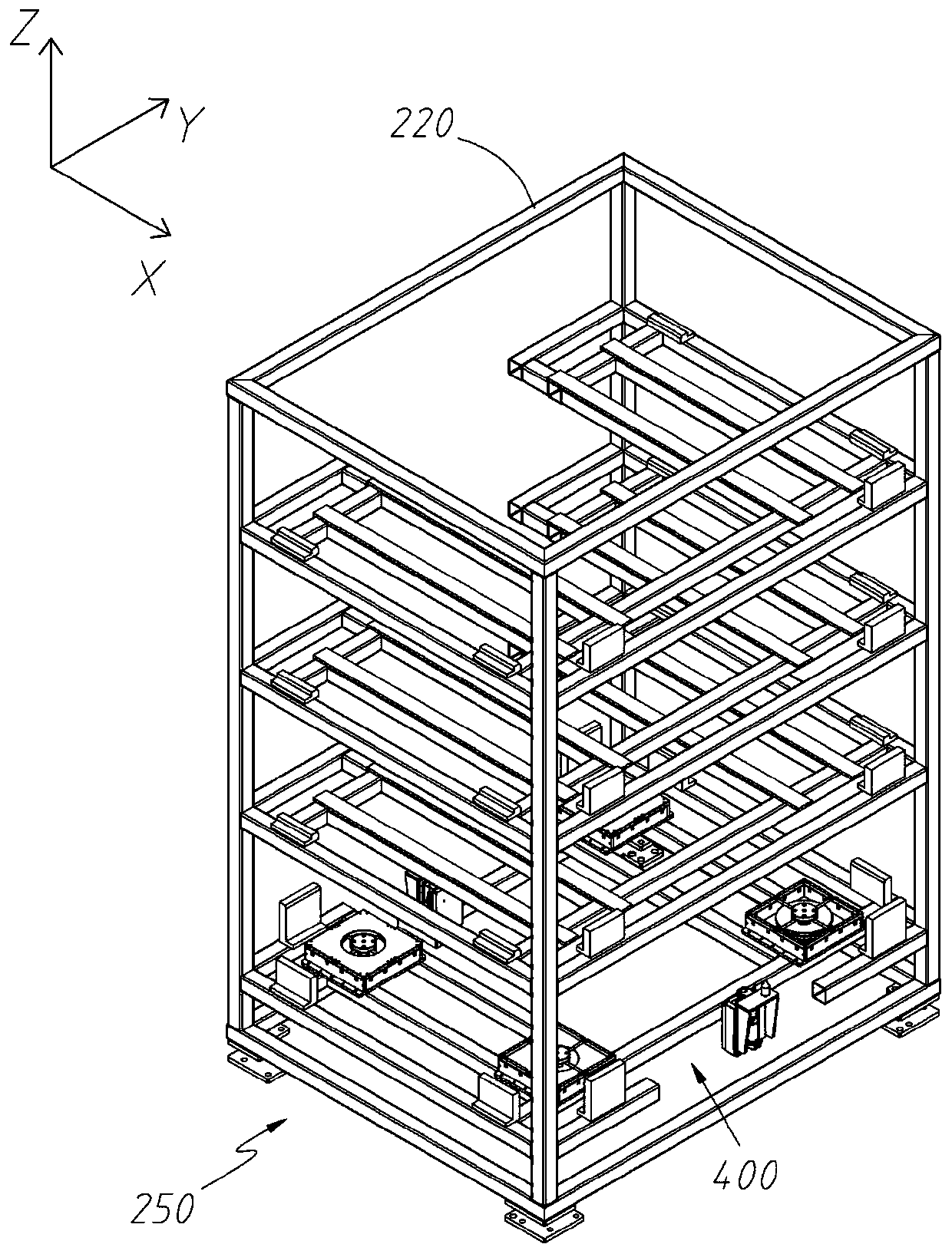
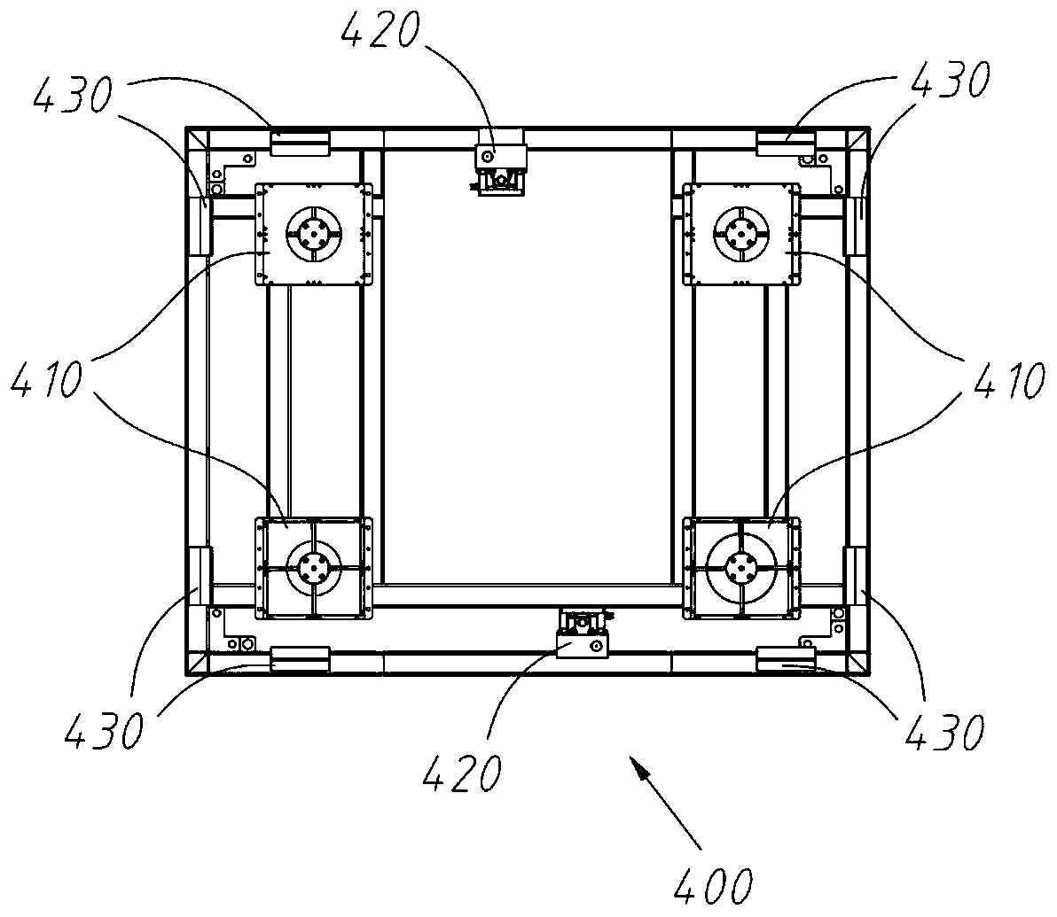
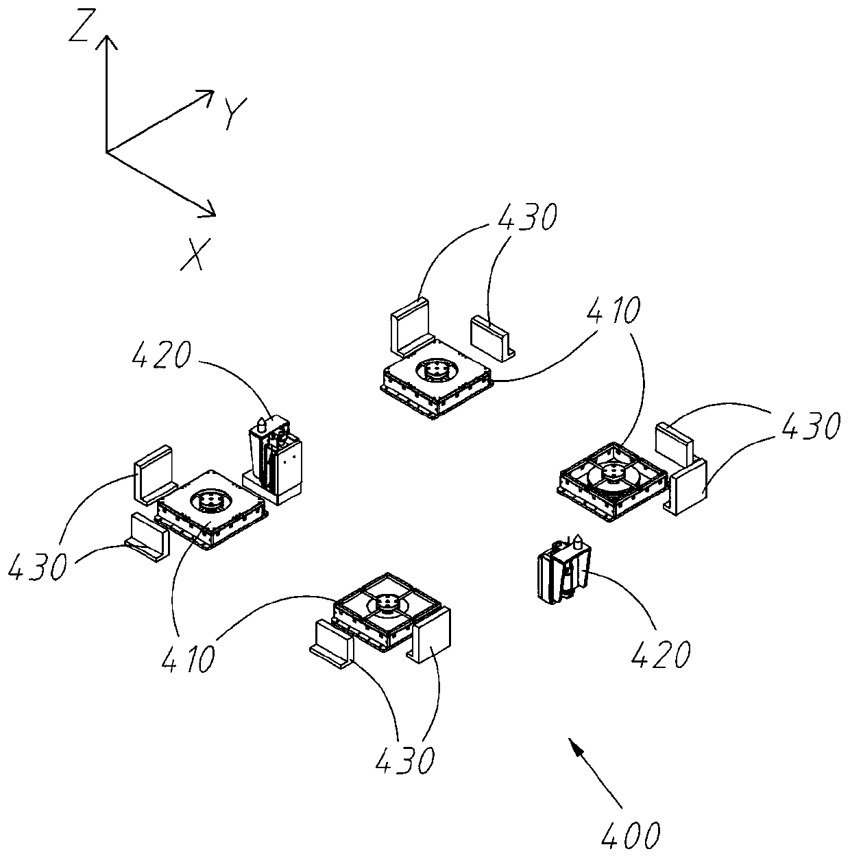
  • Floating positioning mechanism
  • Floating positioning mechanism
  • Floating positioning mechanism

Examples


Embodiment Construction

[0034] The present invention will be further described in detail below in conjunction with the accompanying drawings, and the aforementioned and other objects, features, aspects and advantages of the present invention will become more apparent, so that those skilled in the art can implement them with reference to the description.

[0035] In the drawings, the shapes and dimensions may be exaggerated for clarity, and the same reference numerals will be used throughout to designate the same or like parts.

[0036] In the following description, terms such as center, thickness, height, length, front, back, rear, left, right, top, bottom, upper, lower, etc. are defined with respect to the configuration shown in each drawing , in particular, "height" is equivalent to the dimension from top to bottom, "width" is equivalent to the dimension from left to right, and "depth" is equivalent to the dimension from front to back. They are relative concepts, so it may be based on It changes co...


PUM


Abstract

The invention discloses a floating positioning mechanism comprising at least three floating positioning blocks arranged in the circumferential direction and an even number of guide positioning units,wherein a guide assembly is formed by the guide positioning units in pairs, and the guide positioning units in each the guide assembly are oppositely arranged. According to the floating positioning mechanism in the invention, the accuracy of electrical connection between a deficient battery and a charging connector is greatly improved, the electrical connection success rate is improved, short circuit and potential safety hazards caused by short circuit are effectively avoided, meanwhile, the structure is reasonable in arrangement, the positioning step is simple and effective, and the positioning time is greatly shortened.

Description

technical field [0001] The invention relates to the field of electric vehicles, in particular to a floating positioning mechanism. Background technique [0002] In the process of replacing the fully charged battery of an electric car, it is necessary to remove the deficient battery from the car and put it in the charging compartment, and at the same time take out the fully charged battery from the charging compartment and replace it with the car. In this process, it is necessary to use The charging compartment is used to charge the replaced battery with low power. The existing charging compartment or charging stand lacks the floating positioning function for the battery. As a result, when the replaced low-power battery is electrically connected to the charging connector in the charging compartment, It is prone to problems such as line short circuit caused by low connection accuracy, which leads to charging failure. What's more, line short circuit is easy to cause fire, which...

Claims


Application Information

Patent Timeline
Patent Type & Authority Applications(China)
IPC IPC(8): B60L53/30B60L53/80B25B11/00
CPCB60L53/30B60L53/80B25B11/00Y02T10/70Y02T10/7072Y02T90/12
Inventor 牟东肖申叶庆丰孙庆吴小平
Owner BOZHON PRECISION IND TECH CO LTD
Learn More