Quick-change device for power battery system of electric automobile and battery pack

A power battery pack and power battery technology, which is applied in electric power units, power units, vehicle maintenance, etc., can solve the problems of high cost, low positioning accuracy, complex structure, etc., and achieve reliable and safe connection, stable and reliable fixation, fast Effects of disassembly and installation

Pending Publication Date: 2019-10-15
BEIJING PRIDE NEW ENERGY BATTERY
View PDF0 Cites 8 Cited by
  • Summary
  • Abstract
  • Description
  • Claims
  • Application Information

AI Technical Summary

Problems solved by technology

[0005] The technical problem to be solved by the present invention is to provide a quick-change device and a battery pack for an electric vehicle power battery system in view of the complex structure, low positioning accuracy and high cost of the existing new energy vehicle battery system quick-change device

Method used


Image

  • Quick-change device for power battery system of electric automobile and battery pack
  • Quick-change device for power battery system of electric automobile and battery pack
  • Quick-change device for power battery system of electric automobile and battery pack

Examples


Embodiment 1

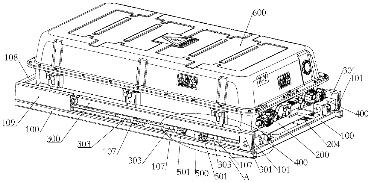
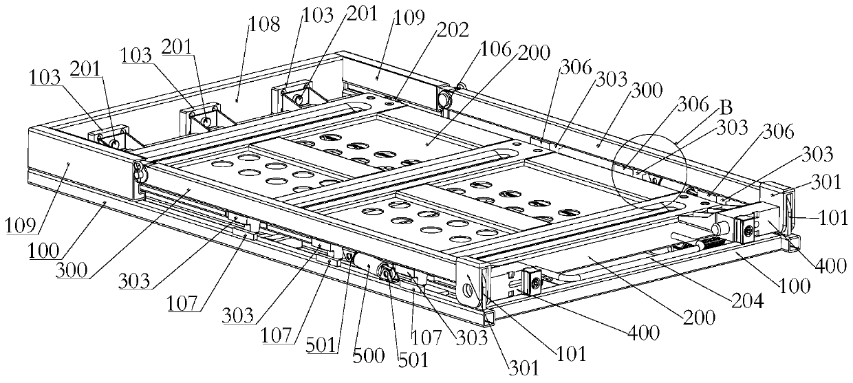
[0045] Such as Figure 1-Figure 10 As shown, a quick-change device for an electric vehicle power battery system in this embodiment includes a fixed bracket 100 and a quick-change bracket 200. The quick-change bracket 200 is used to connect the power battery pack 600 and can be slid into or Slide out the fixed bracket 100; the fixed bracket 100 is hinged with a stop bead 300, and the quick-change bracket 200 or the fixed bracket 100 or the stop bead 300 is provided with a locking structure 400, when the quick-change bracket 200 slides into the fixed bracket 100, the stop bar 300 rotates along the hinge and presses down on the quick-change bracket 200 and realizes the locking structure 400 The locking connection of the fixed bracket 100 , the quick-change bracket 200 and the stop pressure strip 300 is described.

[0046] The quick-change device of this embodiment adopts the stop pressing block and the locking structure, which can realize the mechanical locking of the quick-chan...

Embodiment approach 1

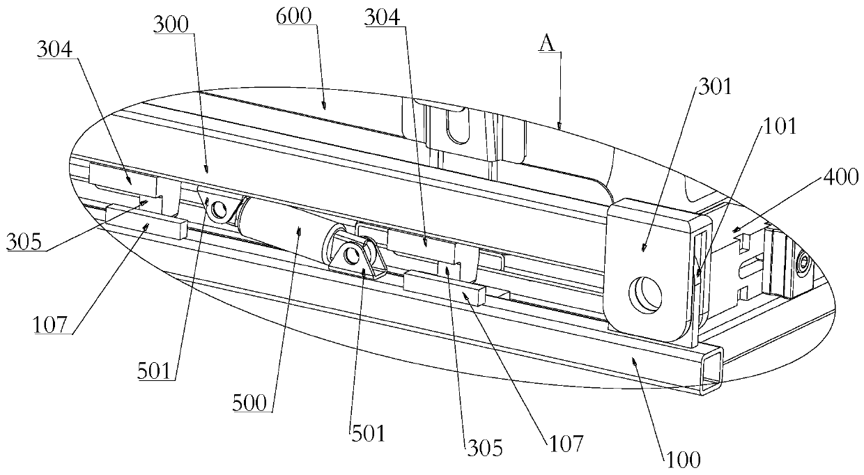
[0049] Embodiment 1, the locking structure 400 is arranged on the stop bead 300, the lock head 301 is arranged on one of the fixed bracket 100 and the quick-change bracket 200, and the lock tongue 101 is arranged on the other, when the quick-change bracket 200 slides When inserted into the fixed bracket 100, the lock head 301 and the locking hole on the deadbolt 101 overlap each other, and then use the locking structure 400 on the stop bead 300 to insert into the two locking holes for locking. . The locking structure 400 can be installed on the inside or outside of the stop bead 300 , and the end structure of the stop bead 300 can also be appropriately improved to adapt to the lock structure 400 . In order to save space, the locking structure 400 can be installed inside the locking bead 300. Since the quick-change bracket 200 slides into the fixed bracket 100, the stopping bead 300 is in an open state, and the locking structure on it 400 does not affect the sliding of the qui...

Embodiment approach 2

[0050] Embodiment 2, the locking structure 400 is arranged on the fixed bracket 100, the lock head 301 is arranged on one of the stopper bar 300 and the quick-change bracket 200, and the lock tongue 101 is arranged on the other, when the quick-change bracket 200 slides When inserted into the fixed bracket 100, the lock head 301 and the locking holes on the dead bolt 101 overlap each other, and then use the locking structure 400 on the fixed bracket 100 to insert into the two locking holes for locking. . The locking structure 400 can be installed on the outside of the fixing bracket 100 , and the structure of the outer edge of the fixing bracket 100 can also be properly improved to adapt to the locking structure 400 .


PUM


Abstract

The invention relates to a quick-change device for a power battery system of an electric automobile and a battery pack. The quick-change device comprises a fixing bracket and a quick-change bracket, and the quick-change bracket is used for connecting a power battery pack and can be clamped into or drawn out of the fixing bracket in a sliding manner; a locking pressing bar is hinged on the fixing bracket, a locking structure is arranged on the quick-change bracket or the fixing bracket or the locking pressing bar, the locking pressing bar rotates along the hinged position to press the quick-change bracket downwards when the quick-change bracket slides into the fixing bracket, and the locking connection of the fixing bracket, the quick-change bracket and the locking pressing bar is achievedthrough the locking structure. According to the invention, a locking pressing block is matched with the locking structure, so that the mechanical locking of the quick-change bracket in X, Y, Z three directions with six degrees of freedom can be achieved, the connection is more reliable and safer, and the quick locking positioning and quick replacement can be achieved by matching the sliding fit ofthe fixing bracket and the quick-change bracket.

Description

technical field [0001] The invention relates to the technical field related to new energy electric vehicles, in particular to a quick-changing device for a power battery system of an electric vehicle and a battery pack. Background technique [0002] With the country's continuous industrial policy support, my country's electric vehicle industry has grown to be the largest in the world. [0003] At present, there are mainly two types of quick-change devices for battery packs of new energy electric vehicles. One is to achieve a locked and fixed connection with the vehicle through a locking structure, and the other is to achieve a connection with the vehicle through bolts. Locking fixed connection between. The quick-change locking structure is relatively complicated, and installation and disassembly require equipment with high positioning accuracy. and positioning is more complicated. [0004] At present, the quick change device of the power battery system of new energy vehic...

Claims


Application Information

Patent Timeline
IPC IPC(8): B60S5/06B60K1/04
CPCB60S5/06B60K1/04B60K2001/0455
Inventor 邓武星赵孟盛力
Owner BEIJING PRIDE NEW ENERGY BATTERY
Why Eureka
Try Eureka