Coupling height measuring scale

A technology of height measurement and coupling, applied in the field of measurement, can solve the problems of difficult measurement, low efficiency, large error, etc., and achieve the effect of rapid measurement

Inactive Publication Date: 2019-10-15
柳州科路测量仪器有限责任公司
View PDF11 Cites 1 Cited by
  • Summary
  • Abstract
  • Description
  • Claims
  • Application Information

AI Technical Summary

Problems solved by technology

[0003] The technical problem to be solved by the present invention is to provide a coupling height measuring ruler, which can solve the problem of using currently commonly used measuring tools (such as depth gauges, dial indicators) to measure the distance from the end surface of the coupling hub to the end surface of the motor spindle. value, due to the conditions of the measurement site, the measurement is difficult, the error is large and the efficiency is low

Method used


Image

  • Coupling height measuring scale
  • Coupling height measuring scale
  • Coupling height measuring scale

Examples


Embodiment Construction

[0024] Below in conjunction with accompanying drawing and embodiment the present invention is further described:

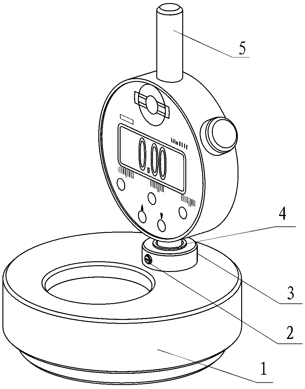
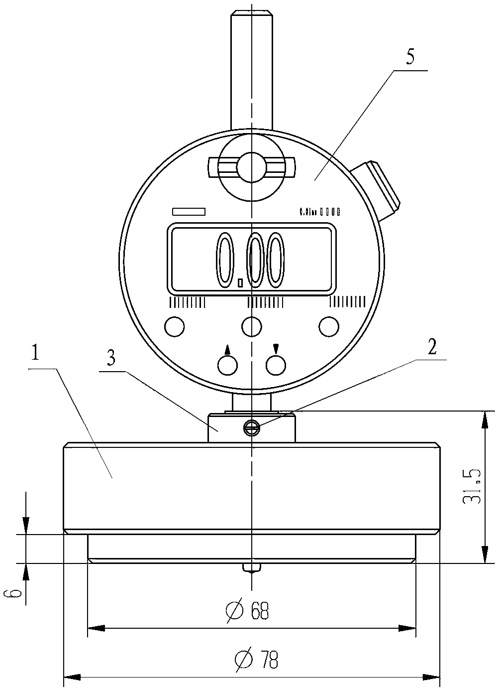
[0025] figure 2 , image 3 and Figure 4 The shaft coupling height measuring ruler, including base 1, table base 3, copper sleeve 4 and digital indicator 5; Figure 5 , Figure 6 and Figure 7 As shown, the lower end of the base 1 is set as a measuring boss 1-3, and the bottom end surface is a positioning surface as a measuring reference, that is, the measuring reference plane S3; the base 1 is provided with a table seat hole 1-1 for installing the table seat 3 and a The observation round hole 1-2 is used to observe the measurement situation, and the observation round hole 1-2 also has the function of reducing weight; the upper side of the base 1 is provided with a mesh pattern 1-4 for easy handling, avoiding slipping, and enhancing rotation flexibility. The structure and precision requirements of table base 3 are as follows Figure 8 , Figure 9 and Fig...


PUM


Abstract

The invention discloses a coupling height measuring scale and relates to the measuring technology field. The measuring scale comprises a pedestal which is provided with a gauge stand hole. The gauge stand hole is provided with a gauge stand, a copper sleeve is arranged in the gauge stand, and a digital display dial indicator is arranged in the copper sleeve and is fixed by a set screw. A lower endof the pedestal is set to be a measured protruding platform, and a side surface of an upper end is provided with an overlapping curve. The side surface of the copper sleeve is provided with a throughgroove with a width of 1 mm. Problems that when commonly used measuring tools, such as a depth gauge and a dial indicator, are used to measure a distance value between an end surface of shaft bossingof the coupling and the end surface of a motor main shaft, measurement is difficult, an error is large and efficiency is low due to a condition limit of a measuring part can be solved.

Description

technical field [0001] The invention relates to the technical field of measurement, in particular to a measuring tool for measuring the distance values ​​from the end faces of shaft hubs of various types of couplings to the end faces of motor main shafts. Background technique [0002] During the assembly process of the coupling shaft and the coupling hub, install various types of couplings as a whole on the shaft with a taper of 1:50, and gently push the couplings along the axial direction to make the coupling shaft The inner hole of the hub (taper 1:50) is attached to the motor shaft (or the pinion shaft of the gearbox) to complete the assembly, such as figure 1 As shown, after the assembly is completed, it is necessary to measure the end face of the motor shaft, that is, the distance A1 from the measurement surface S1 to the measurement reference surface (base positioning surface) S3, and the step surface of the coupling hub, that is, the measurement surface S2 to the meas...

Claims


Application Information

Patent Timeline
Patent Type & Authority Applications(China)
IPC IPC(8): G01B5/06
CPCG01B5/0002G01B5/061
Inventor 王作华徐家海吴锡毅金熠
Owner 柳州科路测量仪器有限责任公司
Why Eureka
Try Eureka