
Compressor piston manufacturing method and piston accurate grinding clamp of centerless cylindrical grinder

A manufacturing method and technology of cylindrical grinding machine, which are applied in the direction of manufacturing tools, grinding machines, and machine tools designed for grinding the rotating surface of workpieces, etc., can solve the problems of low efficiency and do not give how to improve the piston precision and piston production efficiency, etc. Low cost, shortened replacement and adjustment time, and low storage requirements

Pending Publication Date: 2019-08-13
浙江百达精工股份有限公司
View PDF1 Cites 0 Cited by
  • Summary
  • Abstract
  • Description
  • Claims
  • Application Information

AI Technical Summary

Problems solved by technology

When grinding the outer circle of the piston, the perpendicularity of the end to the outer circle can be basically guaranteed by the electromagnetic chuck fixture to be ≤0.003mm, but the cycle time is more than 25 seconds per piece, and the efficiency is low
Although the above method can produce the piston of the rotary piston compressor, it does not give the enlightenment on how to improve the precision of the piston and improve the production efficiency of the piston

Method used


Image

  • Compressor piston manufacturing method and piston accurate grinding clamp of centerless cylindrical grinder
  • Compressor piston manufacturing method and piston accurate grinding clamp of centerless cylindrical grinder
  • Compressor piston manufacturing method and piston accurate grinding clamp of centerless cylindrical grinder

Examples


Embodiment 1

[0037] A method for manufacturing a piston of a rotary piston compressor, comprising the steps of:

[0038] In the first step, the seamless steel pipe made of Gcr15 bearing steel is selected as the raw material, and the seamless steel pipe is in a normalizing state. The seamless steel pipe is cut into piston blanks according to the length of the piston by an automatic cutting machine.

[0039] In the second step, the two end faces of the piston blank are firstly ground with a double-plane grinder, and the parallelism of the two end faces of the piston blank is ≤0.04mm. Then use a centerless cylindrical grinder to grind the outer circular surface of the piston blank. During the process of grinding the outer circular surface of the piston blank, use the piston stacking and clamping device to make the end faces of multiple piston blanks overlap and stick to each other. . Finally, a CNC lathe is used to roughly bore the inner hole of the piston blank.

[0040] In the third step...

Embodiment 2

[0053] The structure and principle of this embodiment are basically the same as that of Embodiment 1, and the basic similarities will not be described repeatedly, only the differences are described, and the differences lie in the fourth step of the piston manufacturing method of the rotary piston compressor. In the fourth step of the embodiment, firstly, use a centerless cylindrical grinder to roughly grind the outer circular surface of the piston blank that has been processed in the third step. The end surfaces of multiple piston blanks are sequentially stacked and closely attached; after rough grinding, the perpendicularity of the end faces of the piston blanks to the outer circular surface is ≤0.04mm. Then the two end surfaces of the piston blank are semi-finely ground by a double surface grinder, and the parallelism of the two end surfaces of the piston blank is ≤0.02mm. Finally, a centerless cylindrical grinder is used to half-grind the outer circular surface of the pisto...

Embodiment 3

[0055] The structure and principle of this embodiment are basically the same as that of Embodiment 1, and the basic similarities will not be described repeatedly, only the differences are described, and the differences lie in the fourth step of the piston manufacturing method of the rotary piston compressor. In the fourth step of the embodiment, firstly, the two end surfaces of the piston blank processed in the third step are roughly ground with a double-surface grinder, and the parallelism of the two end surfaces of the piston blank is ≤0.03mm. Then use a centerless cylindrical grinder to roughly grind the outer circular surface of the piston blank. During the process of rough grinding the outer circular surface of the piston blank, use the piston stacking and clamping device to make the end faces of multiple piston blanks overlap and adhere to each other. ; After rough grinding, the verticality of the end of the piston blank to the outer circular surface is ≤0.04mm. Next, th...


PUM


Abstract

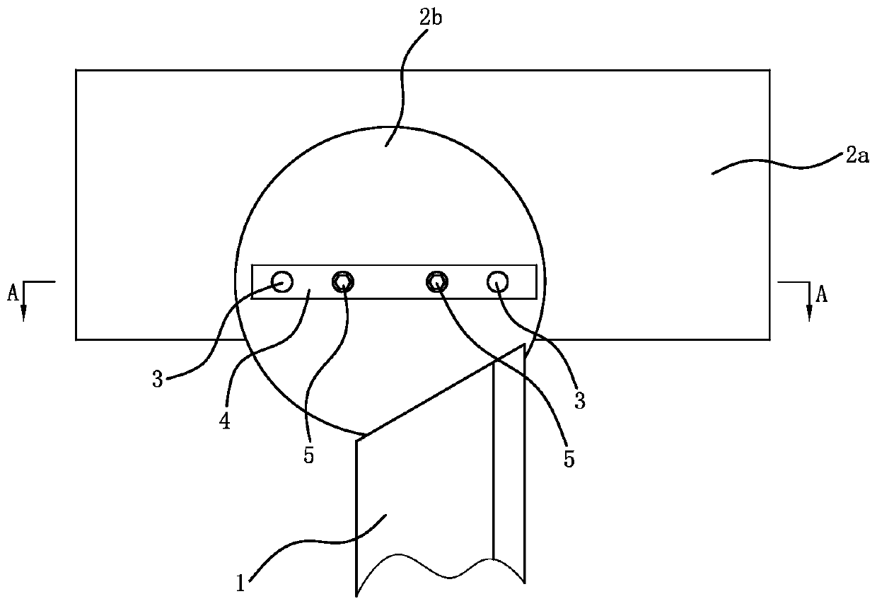
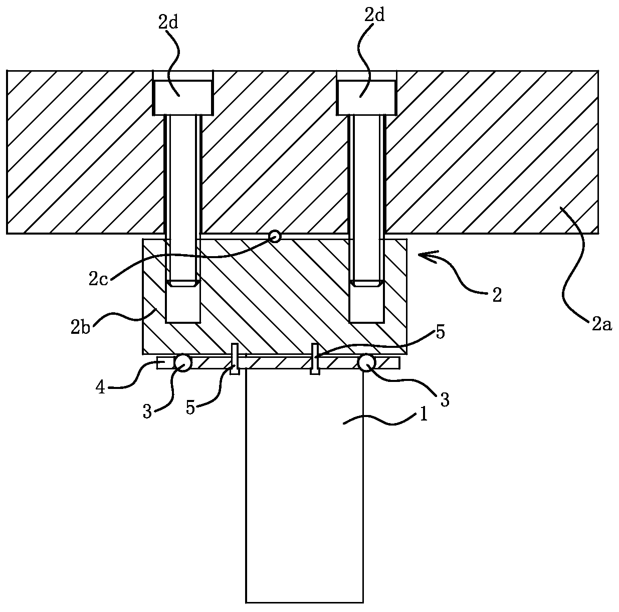
The invention provides a compressor piston manufacturing method and a piston accurate grinding clamp of a centerless cylindrical grinder and belongs to the technical field of compressors. The problemthat existing compressor piston manufacturing and production efficiency fails to meet practical demand is solved. The rotary piston type compressor piston manufacturing method comprises the steps thatfirstly, a seamless steel tube is cut into piston blanks according to the lengths of pistons; secondly, snagging is performed; thirdly, quenching and tempering are performed in sequence; fourthly, coarse grinding and semi-accurate grinding are performed; fifthly, cryogenic treatment is performed; and sixthly, two end surfaces of the piston blanks are subjected to accurate grinding at first, and then accurate grinding is performed on the cylindrical surfaces of the piston blanks one by one. When snagging, coarse grinding and semi-accurate grinding are performed on the piston blanks, the end surfaces are ground before the cylindrical surfaces are ground; and when the cylindrical surface are ground, the end surfaces of the multiple piston blanks are sequentially stacked and tightly attached.The cylindrical surfaces are ground after a stacked and tightly attached "simulative long cylinder" is positioned, the perpendicularity of the two end surfaces to the cylindrical surfaces of the piston blanks is rapidly improved after the piston blanks are subjected to combined mode machining for two to three times.

Description

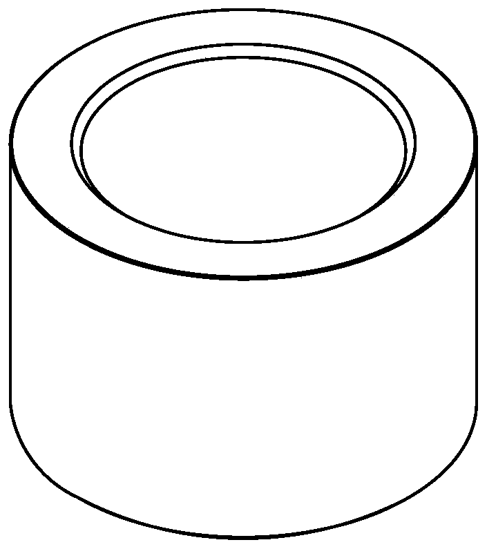
technical field [0001] The invention belongs to the technical field of compressors, and relates to a rotary piston compressor, in particular to a method for manufacturing a piston of a rotary piston compressor. [0002] The invention belongs to the technical field of operation, and relates to a piston fixture, in particular to a compressor piston precision grinding fixture of a centerless cylindrical grinder. Background technique [0003] The work of the piston compressor is completed by the continuous change of the working volume formed by the cylinder, the valve and the piston reciprocating in the cylinder. In the ideal working process, the work completed by the crankshaft of the piston compressor per revolution can be divided into suction, compression and exhaust processes. Such as figure 1 As shown, the piston is a short cylindrical sleeve part, and the two end faces of the piston move between the two large planes of the upper and lower cylinder heads; in order to ensu...

Claims


Application Information

Patent Timeline
IPC IPC(8): B24B1/00B24B5/307
CPCB24B1/00B24B5/307
Inventor 阮吉林张启斌
Owner 浙江百达精工股份有限公司
Learn More