
Track link hot stamping cutting tool edge die

A technology of hot punching and chain rail joints, which is applied in the direction of metal chains, etc., can solve the problems of short service life, low vertical precision of both sides of forgings and the upper and lower sides, and achieve the effect of high verticality and high precision

Pending Publication Date: 2018-04-27
QUANZHOU HENGLIDA ENG MACHINERY
View PDF0 Cites 0 Cited by
  • Summary
  • Abstract
  • Description
  • Claims
  • Application Information

AI Technical Summary

Problems solved by technology

[0003] In view of this, the present invention aims at the problems of short service life of the hot-cutting knife-edge die on the press and low vertical accuracy between the two sides of the forging and the upper and lower sides, and provides a hot-cutting knife-edge die for chain rail sections

Method used


Image

  • Track link hot stamping cutting tool edge die
  • Track link hot stamping cutting tool edge die
  • Track link hot stamping cutting tool edge die

Examples


Embodiment Construction

[0031] The implementation of the present invention will be described in detail below with examples, so as to fully understand and implement the implementation process of how the present invention uses technical means to solve technical problems and achieve technical effects.

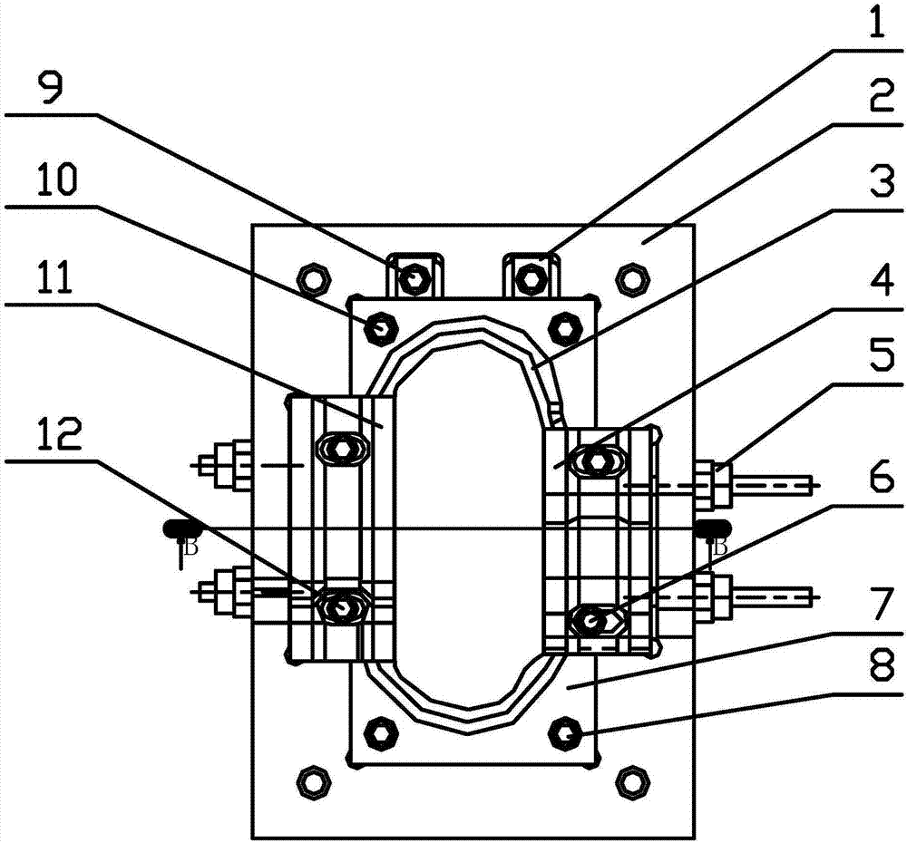
[0032] The invention discloses a chain rail joint hot cutting knife edge device, such as image 3 As shown, the assembled mold frame 2 is included, and the assembled mold frame 2 is provided with a rear blade 3, a hole surface cutter 4, a front blade 7 and a rail surface cutter 11 connected in sequence, and the rear blade 3, the hole surface cutter Knife 4, front blade 7 and rail surface blade 11 enclose closed edge of a knife 13, and the inclination of described closed edge of a knife 13 is 0 °, and described rear blade 3 outside and on assembly frame 2 are provided with blade locking block 1.

[0033] Optionally, one side of the cutting edge of the rear blade 3 and the hole surface cutter 4 is arc-shap...


PUM


Abstract

The invention discloses a track link hot stamping cutting tool edge die which comprises an assembly die frame. The assembly die frame is provided with a rear blade, a hole surface blade, a front bladeand a rail surface blade which are connected in sequence. The rear blade, the hole surface blade, the front blade and the rail surface blade form a step-shaped arc tool edge in a surrounding mode. Ablade locking block is arranged on the outer side of the rear blade and the assembly die frame. The track link hot stamping cutting tool edge die is provided with the four blades, each blade can be repaired and replaced independently, all the cutting tool edges are straight-surface tool edges, no straight extension position exists, and the perpendicularity precision of the two side faces, the upper surface and the lower surface of a forge piece after cutting is high.

Description

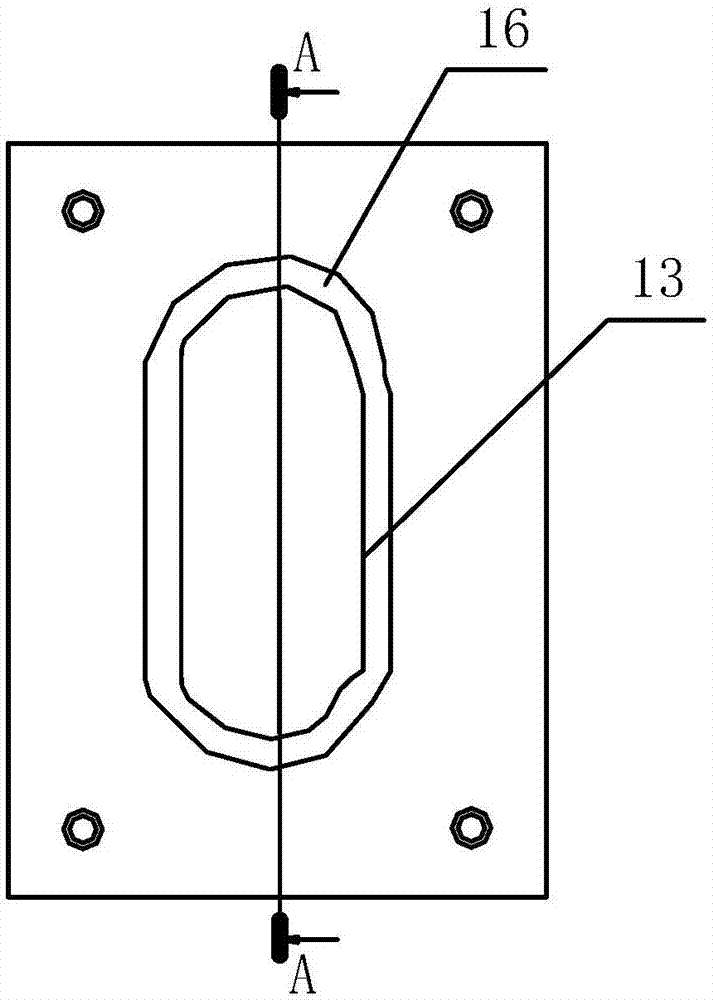
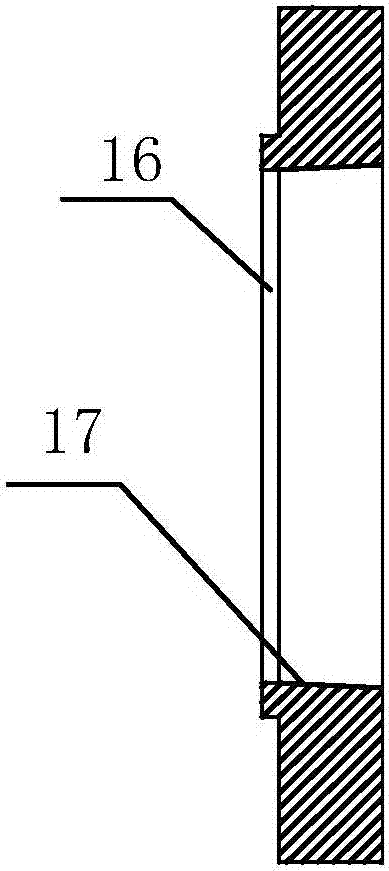
technical field [0001] The invention belongs to the technical field of machine tool processing, and in particular relates to a thermal punching knife-edge mold for chain rail links. Background technique [0002] The hot-cut knife-edge mold device on the traditional press is an integral structure, as shown in the figure figure 1 and figure 2 Shown: the inner frame is used as a knife edge 13, the knife edge has a straight extension position 17 of 10mm, and the other is a slope 18 of 2-5 degrees. The two sides of the forging with this structure are not perpendicular to the upper and lower sides of the forging; the traditional incision cannot be damaged. Replacement requires slot milling, welding and reprocessing, which has a long maintenance period and high cost. And use the hot-cut knife-edge die set on a conventional press. Contents of the invention [0003] In view of this, the present invention provides a thermal punching knife-edge die for chain rail links to solve t...

Claims


Application Information

Patent Timeline
Patent Type & Authority Applications(China)
IPC IPC(8): B21D28/14B21L9/00
CPCB21D28/14B21L9/00
Inventor 吴海波
Owner QUANZHOU HENGLIDA ENG MACHINERY
Learn More