Meteorological radar transmitter fault detection system and method

A fault detection and weather radar technology, applied in radio wave measurement systems, instruments, etc., can solve problems such as failure detection of high-voltage power supply filter regulator Z1 without the design of transmitter high-voltage power supply front-end, so as to improve intelligent fault detection and diagnosis capabilities and The ability to locate fault alarm information, reduce the cost of technical transformation, and improve the effect of improvement feasibility

Active Publication Date: 2019-10-15
舒毅
View PDF6 Cites 1 Cited by
  • Summary
  • Abstract
  • Description
  • Claims
  • Application Information

AI Technical Summary

Problems solved by technology

[0004] For this reason, the embodiment of the present invention provides a weather radar transmitter fault detection system and method to solve the problem that the existing CINRAD / SA weather radar transmitter is not designed for the high voltage power supply filter regulator Z1 at the front end of the high voltage power supply of the transmitter detection, leading to problems that are prone to fault location errors

Method used


Image

  • Meteorological radar transmitter fault detection system and method
  • Meteorological radar transmitter fault detection system and method
  • Meteorological radar transmitter fault detection system and method

Examples


Embodiment 1

[0040] Firstly, the background of the content of this embodiment is introduced.

[0041] (1) Fault events

[0042]At a certain point in time, the weather radar in Quanzhou, Fujian, China frequently issued a fault alarm for the focus coil current of the transmitter system, and the radar system was forced to stand by, making it impossible to conduct operational observations. The staff immediately conducted a preliminary manual on-site investigation.

[0043] According to the contents of radar fault alarm information, radar status and manual on-site troubleshooting operation records, the main fault phenomena of the radar system are as follows: the first transmitter system focusing coil current fault, after 5 failures to automatically clear the fault, the radar system enters the transmitter Fault cycle, transmitter inoperable state, radar system forced to standby due to inoperable alarm; then manual intervention to carry out on-site troubleshooting operations, the transmitter syst...

Embodiment 2

[0075] Corresponding to the above-mentioned embodiment 1, such as Figure 5 As shown, the present embodiment proposes a method for detecting a fault in a weather radar transmitter, the method comprising:

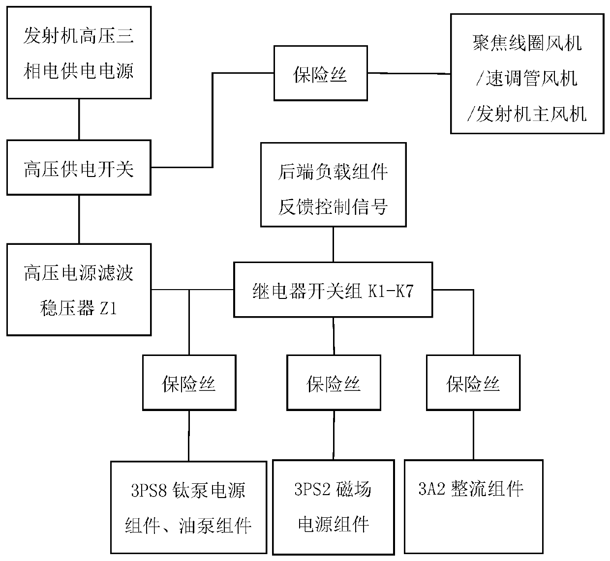
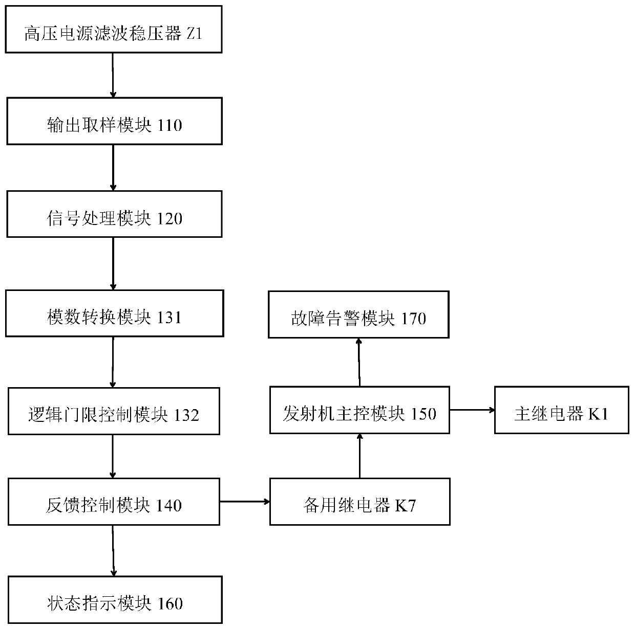
[0076] S210. Sampling the multi-phase output voltage of the high-voltage power supply filter regulator Z1 to obtain a multi-phase voltage sampling signal. The high-voltage power supply filter regulator Z1 is arranged in the front-end circuit of the high-voltage power supply of the transmitter and connected to the high-voltage power supply;

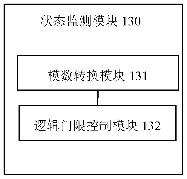
[0077] S220. Comparing the multi-phase voltage sampling signal with a preset voltage threshold to determine whether the operation state of the high-voltage power supply filter regulator Z1 is normal;

[0078] S230. Generate a feedback control signal according to the operating state of the high-voltage power supply filter regulator Z1. The feedback control signal is used to control the pull-in of the backup relay K7 when the high-voltage ...


PUM


Abstract

The embodiment of the invention discloses a meteorological radar transmitter fault detection system and method. A high-voltage power supply filtering voltage stabilizer Z1 in a front-end high-voltagepower supply line of a transmitter is subjected to fault detection circuit design, so that an abnormal operation state of the high-voltage power supply filtering voltage stabilizer Z1 can be timely and effectively detected; when the high-voltage power supply filtering voltage stabilizer Z1 has a fault, a worker can be helped to rapidly and accurately position a fault unit and timely eliminate thefault, so as to improve the intelligent fault detection diagnosis capacity and the fault warning information positioning capacity of a meteorological radar transmitter system; and a standby K7 relay in an original relay switching group in the line is utilized to carry out operation state monitoring on the high-voltage power supply filtering voltage stabilizer Z1, so as to implement state monitoring on the high-voltage power supply filtering voltage stabilizer Z1 and linkage of control of the transmitter system, reduce improvement complexity on the front-end power supply line, improve improvement feasibility and greatly reduce technical transformation cost.

Description

technical field [0001] The embodiments of the present invention relate to the technical field of weather radar, and in particular to a system and method for detecting a fault of a weather radar transmitter. Background technique [0002] CINRAD / SA weather radar is a commonly used Doppler weather radar. The high-voltage power supply front-end circuit of the existing CINRAD / SA weather radar transmitter is equipped with a high-voltage power supply filter regulator Z1, and a high-voltage power supply filter regulator Z1. The back-end load components include 3PS2 magnetic field power supply components, 3A2 rectifier components, 3PS8 titanium pump power supply components and oil pump components, etc. The feedback control signal of the transmitter system acts on the relay switch group, and the switch group includes relays K1-K7, of which K1 is the main relay , used for high-voltage power supply control of each back-end load component, K2-K6 is the operation control switch of each ba...

Claims


Application Information

Patent Timeline
Patent Type & Authority Applications(China)
IPC IPC(8): G01S7/40
CPCG01S7/4008
Inventor 舒毅杨苏勤苏礼贤王聪晓李智成杜言霞杨泽鑫
Owner 舒毅
Why Eureka
Try Eureka