Small-size high-voltage-resistance electromagnetic relay

An electromagnetic relay, high withstand voltage technology, applied in the direction of electromagnetic relay, electromagnetic relay details, relays, etc., can solve problems such as circuit breakers cannot be used, fatigue breakage, product failure, etc., to improve mechanical fatigue resistance and avoid early The effect of fatigue fracture and avoiding product failure

Pending Publication Date: 2019-10-15
XIAMEN HONGFA ELECTROACOUSTIC CO LTD
View PDF0 Cites 1 Cited by
  • Summary
  • Abstract
  • Description
  • Claims
  • Application Information

AI Technical Summary

Problems solved by technology

[0003] Electromagnetic relays have been widely used in various fields. In some application fields, there are high requirements for withstand voltage between contacts, between contacts and coils, and between contact groups. For example, in 5G power system applications Among them, there are higher requirements for electromagnetic relays. Usually, it is required that the lightning strike voltage between disconnected contacts must meet more than 10KV. If two or more contact groups are involved, the lightning strike resistance between contact groups The voltage also needs to meet more than 10KV, and the lightning strike voltage between the contact and the coil also needs to meet more than 10KV. The electromagnetic relay of the prior art usually cannot meet the above requirements. In the prior art, products with a withstand voltage of more than 10KV are all used Circuit breakers are large in size and expensive, and 5G power supply system equipment is mainly installed on street light poles, building exteri

Method used


Image

  • Small-size high-voltage-resistance electromagnetic relay
  • Small-size high-voltage-resistance electromagnetic relay
  • Small-size high-voltage-resistance electromagnetic relay

Examples


Embodiment

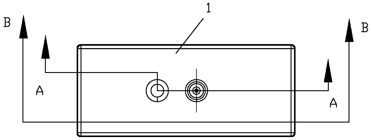
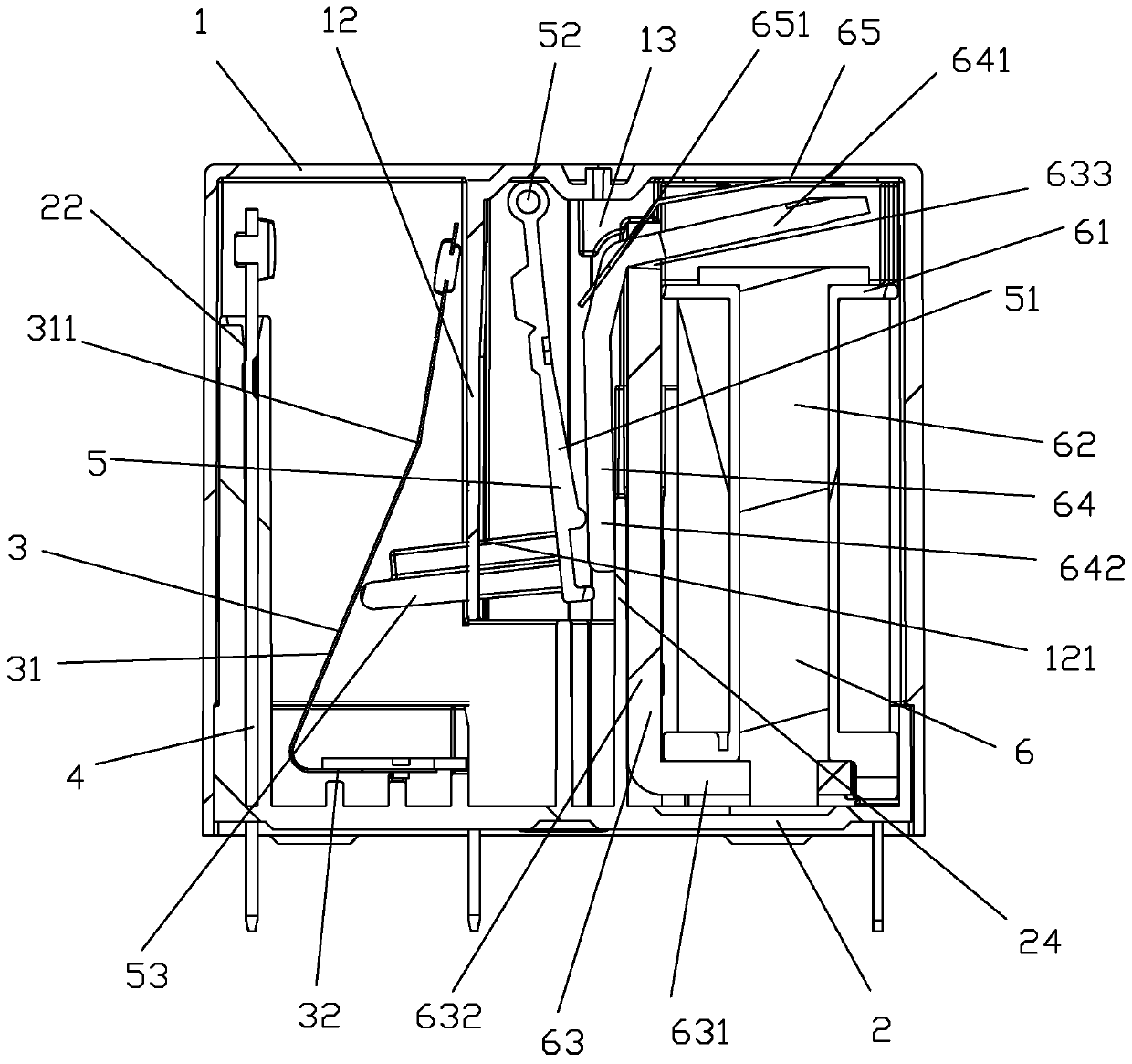
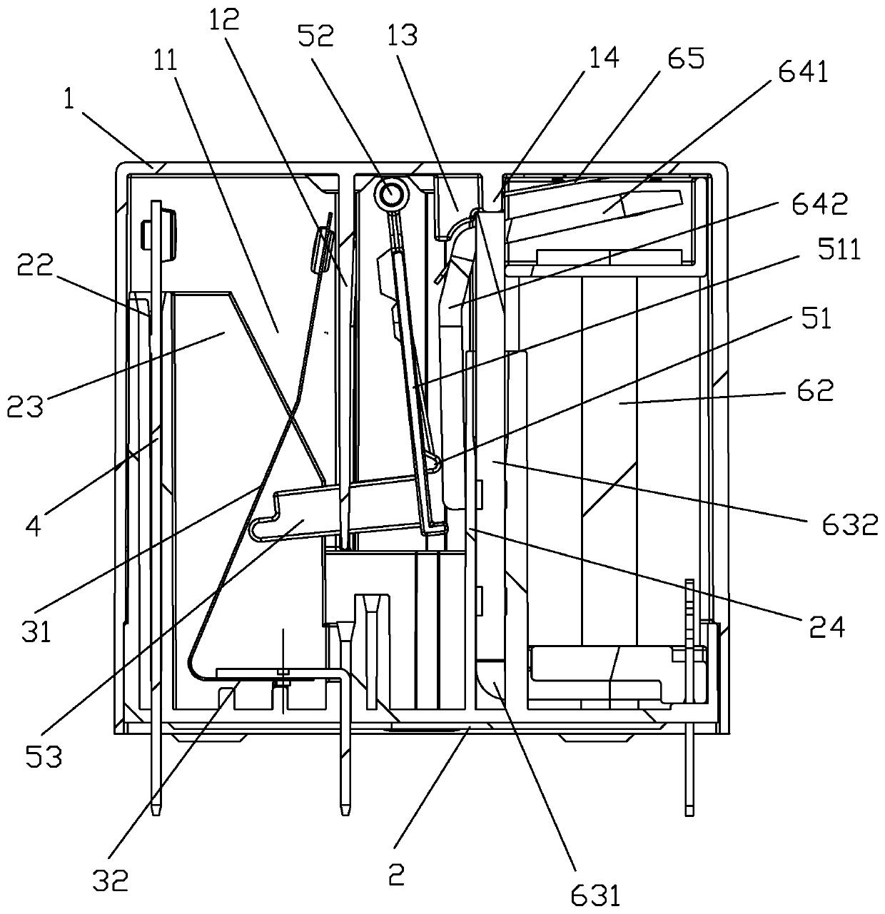
[0040] see Figure 1 to Figure 10 Shown, a kind of small volume high withstand voltage electromagnetic relay of the present invention comprises shell 1, base 2, moving reed 3, static spring 4, push card 5 and magnetic circuit part 6; Shell 1 is connected with base 2; The bottoms of the static spring 4, the moving reed 3 and the magnetic circuit part 6 are respectively installed on the base 2 and accommodated in the housing 1, and the push card 5 is fitted between the moving reed 3 and the magnetic circuit part 6; In this embodiment, the moving reed 3 is L-shaped, and the L-shaped vertical side 31 of the moving reed 3 is inclined, so as to increase the distance between the contacts and meet the requirement of disconnecting the contacts. Requirements for high pressure resistance; the L-shaped horizontal side 32 of the moving reed 3 is plugged and fixed on the base 2; ), in this embodiment, the push card 5 is L-shaped, and the top of the L-shaped vertical side 51 of the push car...


PUM


Abstract

The invention discloses a small-size high-voltage-resistance electromagnetic relay. The small-size high-voltage-resistance electromagnetic relay comprises a shell, a base, a movable reed, a static reed, a pushing clamp and a magnetic circuit portion; the shell is connected with the base; the bottom portions of the static reed, the movable reed and the magnetic circuit portion are installed on thebase, the pushing clamp is cooperated between the movable reed and the magnetic circuit portion; a large distance is arranged between the movable reed and the static reed; a high wall is protruded atthe base upwards, the pushing clamp comprises a vertical piece and a push arm horizontally connected to the vertical piece, the top portion of the vertical piece of the pushing clamp is rotationally installed at the top portion of the high wall of the base through a rotating shaft, and the push arm of the pushing clamp is cooperated with the position, close to the root, of the movable reed. The small-size high-voltage-resistance electromagnetic relay can achieve high pressure resistance under the condition of a small volume, can avoid early fatigue fracture of the movable reed due to large-stroke movement, and can avoid the phenomenon that a pushing clamp falls off to cause product failure under the condition of a large vibration impact.

Description

technical field [0001] The invention relates to the technical field of relays, in particular to a small-volume high-voltage-resistant electromagnetic relay. Background technique [0002] The relay is an electronic control device, which has a control system (also known as the input circuit) and a controlled system (also known as the output circuit), usually used in automatic control circuits, it actually uses a smaller current to control a larger An "automatic switch" of electric current. Therefore, it plays the role of automatic adjustment, safety protection, and conversion circuit in the circuit. [0003] Electromagnetic relays have been widely used in various fields. In some application fields, there are high requirements for withstand voltage between contacts, between contacts and coils, and between contact groups. For example, in 5G power system applications Among them, there are higher requirements for electromagnetic relays. Usually, it is required that the lightning...

Claims


Application Information

Patent Timeline
IPC IPC(8): H01H50/04H01H50/64
CPCH01H50/041H01H50/64
Inventor 王照杉谭忠华李东侠
Owner XIAMEN HONGFA ELECTROACOUSTIC CO LTD
Why Eureka
Try Eureka