
A radio frequency switch device realizing high isolation and no standing wave change

A radio frequency switch and high isolation technology, applied in the field of radio frequency switch devices, can solve the problems of changes in the standing wave ratio of radio frequency signals, difficulty in improving the isolation of radio frequency switches, etc., and achieve the effect of high isolation

Active Publication Date: 2021-01-12
成都同相科技有限公司 +1
View PDF4 Cites 0 Cited by
  • Summary
  • Abstract
  • Description
  • Claims
  • Application Information

AI Technical Summary

Problems solved by technology

[0004] In order to solve the problems that the isolation of the existing radio frequency switch is difficult to improve and the standing wave ratio of the radio frequency signal will change when the switch is turned on and off, the purpose of the present invention is to provide a radio frequency switch device that achieves high isolation and no standing wave change, which can Meet the application scenarios that require precise control of signal isolation and phase, such as atomic clocks, radars, and quantum computers

Method used


Image

  • A radio frequency switch device realizing high isolation and no standing wave change
  • A radio frequency switch device realizing high isolation and no standing wave change
  • A radio frequency switch device realizing high isolation and no standing wave change

Examples


Embodiment 1

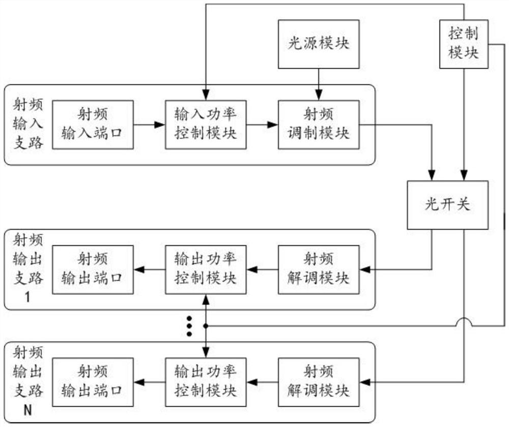
[0030] Such as figure 1 As shown, the radio frequency switch device for achieving high isolation and no standing wave change provided in this embodiment includes a light source module, a radio frequency input branch, a radio frequency output branch and an optical switch, wherein the radio frequency input branch includes a series A radio frequency input port and a radio frequency modulation module, the radio frequency modulation module is also connected to the light source module, the radio frequency output branch includes a series radio frequency demodulation module and a radio frequency output port, and the optical switch is connected in series between the radio frequency modulation module and the radio frequency output port Between the radio frequency demodulation modules.

[0031] Such as figure 1As shown, in the specific structure of the radio frequency switch device, the light source module is used to generate an optical carrier signal that can be modulated at a high spe...


PUM


Abstract

The invention relates to the field of radio frequency devices, and discloses a radio frequency switching device for realizing high isolation and no standing wave change. On one hand, a radio frequencymodulation module and a radio frequency demodulation module are respectively arranged in a radio frequency input branch and a radio frequency output branch; photoelectric modulation and demodulationcan be carried out on a radio frequency signal; and on the other hand, on-off control can be performed on a middle modulated optical signal by arranging an optical switch between a radio frequency input branch and a radio frequency output branch, so that the purpose of performing indirect on-off control or path switching on the transmitted radio frequency signal is achieved. Complete light isolation can be realized on the dimmed signal; and meanwhile, the input radio frequency signals always belong to the same working state in the switching process of the switch, and the load is not changed atall, so that echo signals of the input port can be kept stable all the time, and the phase of the input radio frequency signals cannot be influenced by the on-off of the switch.

Description

technical field [0001] The invention belongs to the field of radio frequency devices, in particular to a radio frequency switch device capable of realizing high isolation and no standing wave change. Background technique [0002] The radio frequency switch, also known as the microwave switch, is used to control the conversion of the microwave signal channel. It is essentially a microwave transmission device that routes high-frequency signals on and off. Therefore, it is widely used in microwave test systems, as well as for instruments and test Signal routing between devices, and for carrier phone switching, cable TV signal switching or cable TV signal switching and other fields. Existing radio frequency switches are mainly divided into two categories: mechanical relay switches and solid-state switches. The former is based on the theory of electromagnetic induction and mainly relies on mechanical contacts as the switching mechanism. The latter is based on electronic switching...

Claims


Application Information

Patent Timeline
Patent Type & Authority Patents(China)
IPC IPC(8): H04B1/04H04B10/54H04B10/548
CPCH04B1/0483H04B10/54H04B10/548H04B2210/006
Inventor 高超王崔州
Owner 成都同相科技有限公司
Learn More