Ganglion puncture needle

A ganglion cyst and puncture needle technology, which is applied in the field of puncture needles, can solve the problems of inability to realize cyst fluid agitation, low cyst fluid agitation efficiency, slow dredging efficiency, etc., and achieve the effect of reducing the probability of blockage, good effect and high agitation efficiency

Inactive Publication Date: 2019-10-18
朱世新
View PDF1 Cites 0 Cited by
  • Summary
  • Abstract
  • Description
  • Claims
  • Application Information

AI Technical Summary

Problems solved by technology

However, the above scheme also has the following problems: (1) Since the active magnetic sliding sleeve and the passive magnetic sliding sleeve use magnetic force to cooperate and move synchronously, since the two are separated by the needle seat during the movement, the magnetic force is relatively small, and with the The increase in the number of long-term use will cause demagnetization of the two, which may cause the problem that the active magnetic sliding sleeve cannot drive the passive magnetic sliding sleeve during the movement of the two, resulting in the passive magnetic sliding sleeve being unable to drive the movement of the hook portion of the elastic strip, thus It is impossible to stir the cyst fluid in the cyst; (2) Since the passive magnetic sliding sleeve drives the hook part to move only along the vertical direction of the side hole, the stirring efficiency of the cyst fluid in the cyst is low; (3 ) Since the passive magnetic sliding sleeve drives the elastic strip to move along the axial direction of the needle body, when the needle cavity is blocked, the active magnetic sliding sleeve needs to be moved up and down greatly, and the dredging efficiency is relatively slow

Method used


Image

  • Ganglion puncture needle
  • Ganglion puncture needle
  • Ganglion puncture needle

Examples


Embodiment Construction

[0022] The following will clearly and completely describe the technical solutions in the embodiments of the present invention with reference to the accompanying drawings in the embodiments of the present invention. Obviously, the described embodiments are only some, not all, embodiments of the present invention. Based on the embodiments of the present invention, all other embodiments obtained by persons of ordinary skill in the art without making creative efforts belong to the protection scope of the present invention.

[0023] see Figure 1-5 , the present invention provides a technical solution:

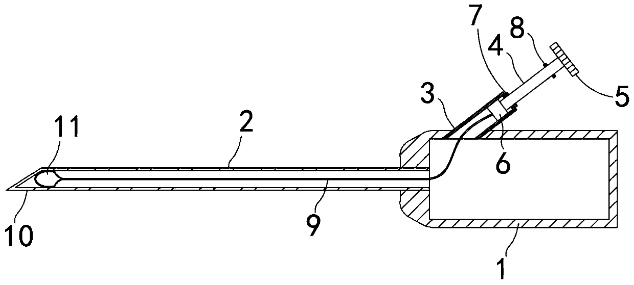
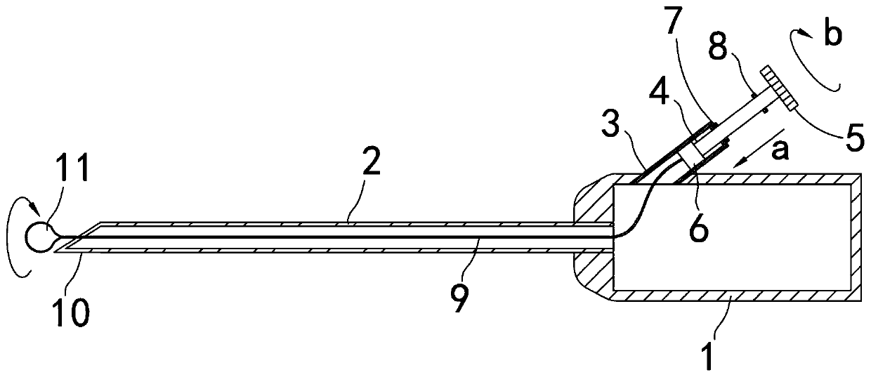
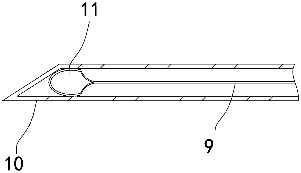
[0024] A ganglion cyst puncture needle, comprising a connecting tube 1, a push rod 4 and an elastic strip 9, the head end of the connecting tube 1 is open, and the tail is provided with a needle body 2, and the tail of the needle body 2 is a spiked part 10 , the needle body 2 close to the sharp part 10 is provided with a penetration hole 12, the tube wall of the connecting tube 1 ...


PUM


Abstract

The invention relates to the technical field of puncture needles, in particular to a ganglion puncture needle. The ganglion puncture needle comprises a connecting pipe, a push rod and a spiral elasticstrip, wherein the head end of the connecting pipe is provided with an opening, the tail of the connecting pipe is provided with a needle body, the tail of the needle body is a sharp part, the portion, close to the sharp part, of the needle body is provided with penetration holes, the pipe wall of the connecting pipe is obliquely provided with a branch pipe communicated with the connecting pipe,the head end of the elastic strip is located in the branch pipe, the tail end of the elastic strip penetrates through the connecting pipe to reach the sharp part, the push rod is movably inserted in the branch pipe, and the tail end of the elastic strip is provided with an annular part formed by bending. The ganglion puncture needle has the advantages that the annular part rotates to constantly stir cyst fluid in the cyst, so that the cyst fluid moves to the sharp part, the cyst fluid is accordingly uniform and easy to absorb, it is ensured that the cyst fluid is sucked thoroughly, meanwhile,the rotary motion of the elastic strip is utilized to avoid the situation that substances in the cyst fluid block a needle cavity of the needle body, and the dredging effect on the needle cavity of the needle body is good.

Description

technical field [0001] The invention relates to the technical field of puncture needles, in particular to a ganglion cyst puncture needle. Background technique [0002] Ganglion cyst is a cystic mass that occurs in the tendon sheath of a joint, a condition caused by degeneration of connective tissue around the joint capsule. Cysts contain colorless transparent or orange, light yellow thick mucus, mostly in the dorsum of the wrist and dorsum of the foot. Using puncture to extract the cyst fluid, and then injecting adrenocortical hormone or hyaluronidase has a certain effect on the treatment of ganglion cysts, and the trauma is small. However, because the cyst fluid is relatively viscous and has poor fluidity, it is difficult to aspirate thoroughly, which leads to the recurrence of ganglion cysts after puncture treatment. In addition, because the cyst fluid is relatively viscous, it is easy to block the puncture needle during aspiration, resulting in poor aspiration, and the...

Claims


Application Information

Patent Timeline
Patent Type & Authority Applications(China)
IPC IPC(8): A61B17/34A61M1/00
CPCA61B17/3478A61M1/0023
Inventor 朱世新
Owner 朱世新
Why Eureka
Try Eureka