Single-layer microfluidic chip with three-dimensional focusing function

A microfluidic chip, single-layer technology, applied in laboratory utensils, laboratory containers, chemical instruments and methods, etc., can solve the problems of reduced analysis and sorting accuracy, flow channel congestion, complex structure, etc. Improve analysis or sorting accuracy, prevent flow channel blockage, and achieve the effect of three-dimensional focusing

Pending Publication Date: 2019-10-18
SUZHOU INST OF BIOMEDICAL ENG & TECH CHINESE ACADEMY OF SCI +1
View PDF0 Cites 2 Cited by
  • Summary
  • Abstract
  • Description
  • Claims
  • Application Information

AI Technical Summary

Problems solved by technology

However, traditional microfluidic chips are processed based on planar design and have equal depths in the direction perpendicular to the substrate. Therefore, samples can only be arranged along the plane direction parallel to the substrate, but cannot be arranged in the direction perpendicular to the substrate. To achieve effective aggregation arrangement, the microfluidic chip based on this design can only achieve the so-called "one-dimensional focusing", which reduces the accuracy of analysis and sorting
[0004] In order to solve the three-dimensional focusing problem on this microfluidic chip, it is often necessary to achieve three-dimensional focusing by stacking multi-layer chips, but this method has a complex structure, high design difficulty, and high processing costs, which cannot be achieved in practical applications. good promotion
[0005] On the other hand, the outlet channel of the existing microfluidic chip generally includes at least one sorting channel and a waste liquid channel, so that a protrusion relative to the direction of fluid flow will be formed at the intersection of the two outlet channels, and a bulge will be formed in the raised area. The stagnation point in the flow, the existence of this stagnation point causes cells or particles to adhere to it, which in turn causes the aggregation of cells or particles, resulting in changes in the stable microfluidic flow state, reducing the accuracy of analysis or sorting, and also causing flow Channel congestion, sample contamination, purity drop, etc.

Method used


Image

  • Single-layer microfluidic chip with three-dimensional focusing function
  • Single-layer microfluidic chip with three-dimensional focusing function
  • Single-layer microfluidic chip with three-dimensional focusing function

Examples


Embodiment 1

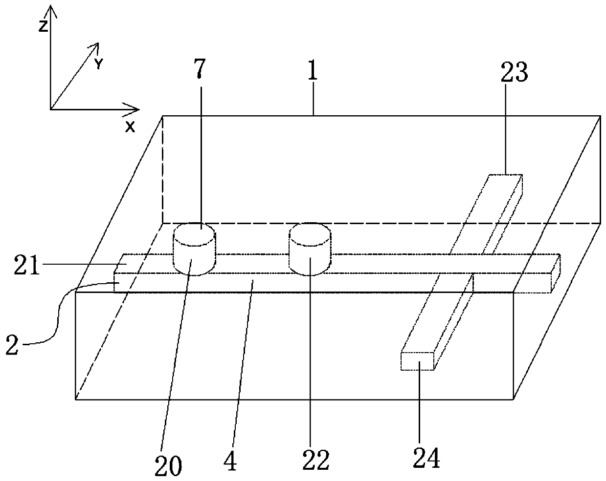
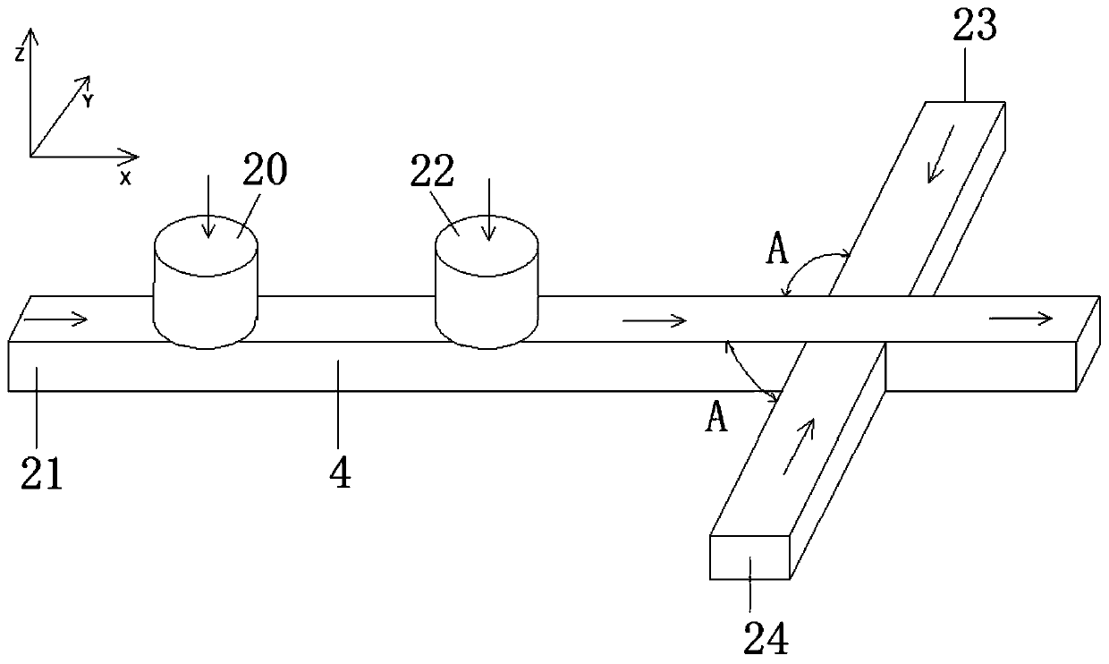
[0035] like Figure 1-2 As shown, a single-layer microfluidic chip with a three-dimensional focusing function in this embodiment includes a single-layer microfluidic chip main body 1, a main channel 4 and a focusing module 2 arranged in the single-layer microfluidic chip main body 1 , the focusing module 2 includes a sample pipeline 20 communicated with the main channel 4, and a first sheath liquid pipeline for realizing the focus of the sample flow in the main channel 4 in the vertical direction (XZ plane in the figure) communicated with the main channel 4 21 and the second sheath fluid pipeline 22, the third sheath fluid pipeline 23 and the fourth sheath fluid pipeline 23 and the fourth sheath fluid that communicate with the main channel 4 and are used to focus the sample flow in the main channel 4 in the horizontal direction (XY plane in the figure). Line 24:

[0036] The first sheath fluid pipeline 21 is on the same streamline as the main channel 4, the second sheath flui...

Embodiment 2

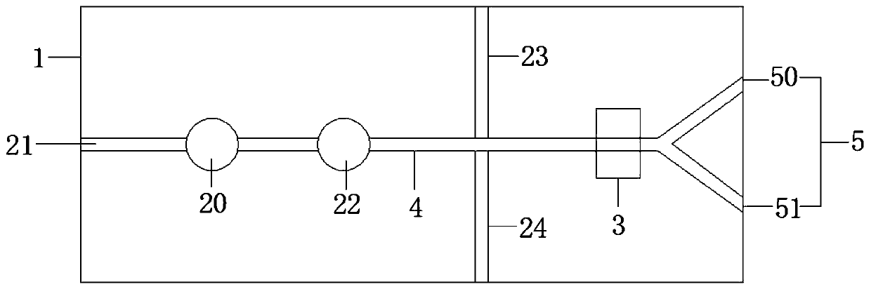
[0044] refer to image 3 , which is a further preferred embodiment on the basis of the above-mentioned embodiment 1, the microfluidic chip also includes a sorting module 3 arranged on the main channel 4, and after the main channel 4 passes through the sorting module 3 Two outlet channels 5 are bifurcated at the outlet end of the single-layer microfluidic chip main body 1, which are respectively a sorting channel 50 (and a target channel, which communicates with the target outlet), and a waste liquid channel 51 ( connected to the waste liquid outlet), a countercurrent sheath fluid channel 6 communicating with the main channel 4 is provided between the two outlet channels 5, and the countercurrent sheath fluid channel 6 is connected to the main channel The flow direction of the fluid in channel 4 is opposite to the reverse flow of the sheath fluid.

[0045] After the sample passes through the sorting module 3 , target particles enter the sorting channel 50 , and non-target cell...

Embodiment 3

[0048] refer to Figure 4-8 , as a further preferred embodiment on the basis of embodiment 2, a flow guide device 8 is arranged in the main channel 4 at the intersection of the two outlet channels 5, and the flow guide device 8 is located between the main channel 4 and the countercurrent sheath liquid flow The junction of the channel 6; the guide device 8 includes two guide vanes 80 connected to each other, the angle between the two guide vanes 80 is the same as the angle between the two outlet flow channels 5, and the two guide vanes 80 are the same. The flow vanes 80 are symmetrically distributed on both sides of the center line of the reverse flow sheath fluid channel 6 , and the two guide vanes 80 are respectively parallel to the two liquid outlet channels 5 . Wherein, a tapered flow guide hole 81 is vertically penetrating through the flow guide plate 80 along the thickness direction, and the size of the tapered flow guide hole 81 gradually increases from the side close to...


PUM


Abstract

The invention discloses a single-layer microfluidic chip with three-dimensional focusing function. The single-layer microfluidic chip comprises a single-layer microfluidic chip main body, and a main runner and a focusing module that are arranged disposed in the single-layer microfluidic chip main body. The focusing module includes a sample pipeline communicated with the main runner, a first sheathliquid pipeline and a second sheath liquid pipeline that are communicated with the main runner to realize focusing of a sample flow in the main runner in a vertical direction, and a third sheath liquid pipeline and a fourth sheath liquid pipeline that are communicated with the main runner to realize focusing of the sample flow in the main runner in a horizontal direction. By means of the sheath liquid in the first sheath liquid pipeline and the second sheath liquid pipeline, the single-layer microfluidic chip provided by the invention realizes focusing of the sample flow in the XZ plane, andthrough the third sheath liquid pipeline and the fourth sheath liquid pipeline, focusing in the XY plane can be realized, thereby realizing three-dimensional focusing. The single-layer microfluidic chip enables single-row flow of the sample in the main runner, not only improves the precision of analysis and sorting, but also has a simple structure and is low in cost.

Description

technical field [0001] The invention relates to the field of microfluidic chips, in particular to a single-layer microfluidic chip with a three-dimensional focusing function. Background technique [0002] The development of modern life science is inseparable from the innovation and progress of research methods, especially the development of separation, analysis and testing methods for micron or submicron particles, which has greatly promoted the development of modern life science to a higher, deeper and more refined level. level development. Since 1990, when scientists first proposed a miniature total analysis system, microfluidic technology has gradually become an important development frontier in the current microscopic field of analysis. It can integrate the sample preparation, reaction and other operations of biological, chemical, and medical analysis processes into a single micron scale. On the chip, the whole process of analysis is automatically completed, which is ca...

Claims


Application Information

Patent Timeline
Patent Type & Authority Applications(China)
IPC IPC(8): B01L3/00
CPCB01L3/5027
Inventor 宋飞飞王策马玉婷吴云良陈忠祥裴智果严心涛钟金凤王红梅闫龙
Owner SUZHOU INST OF BIOMEDICAL ENG & TECH CHINESE ACADEMY OF SCI
Why Eureka
Try Eureka