
Grease lubrication spindle

A grease-lubricated, spindle technology, applied in the field of grease-lubricated spindles, can solve the problems of emergency stop of the spindle, uneven force on the workpiece, damage to the motor, etc., to prevent damage to the tool and its motor, improve production and processing quality, and increase the contact area. Effect

Active Publication Date: 2019-10-18
安徽航睿电子科技有限公司
View PDF11 Cites 1 Cited by
  • Summary
  • Abstract
  • Description
  • Claims
  • Application Information

AI Technical Summary

Problems solved by technology

[0003] However, when the main shaft in the lathe clamps workpieces with different sizes and cylindrical structures, it is easy to cause uneven force on the workpiece, resulting in deep indentations on the surface of the workpiece with poor hardness, and waste chips are easy to enter during the production process. The inside of the main shaft affects the clamping quality of the next workpiece. When the tool is damaged or the operation error makes the tool directly touch the workpiece, the main shaft cannot rotate when the tool is easily touched, and the main shaft stops suddenly, which in turn easily damages the tool and the main body of the main shaft. In severe cases, it is easy Cause motor overload damage

Method used


Image

  • Grease lubrication spindle
  • Grease lubrication spindle
  • Grease lubrication spindle

Examples


Embodiment Construction

[0022] In order to make the technical means, creative features, goals and effects achieved by the present invention easy to understand, the present invention will be further described below in conjunction with specific embodiments.

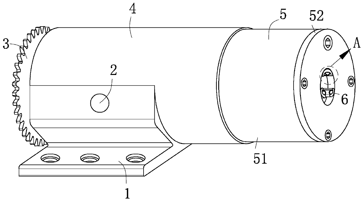
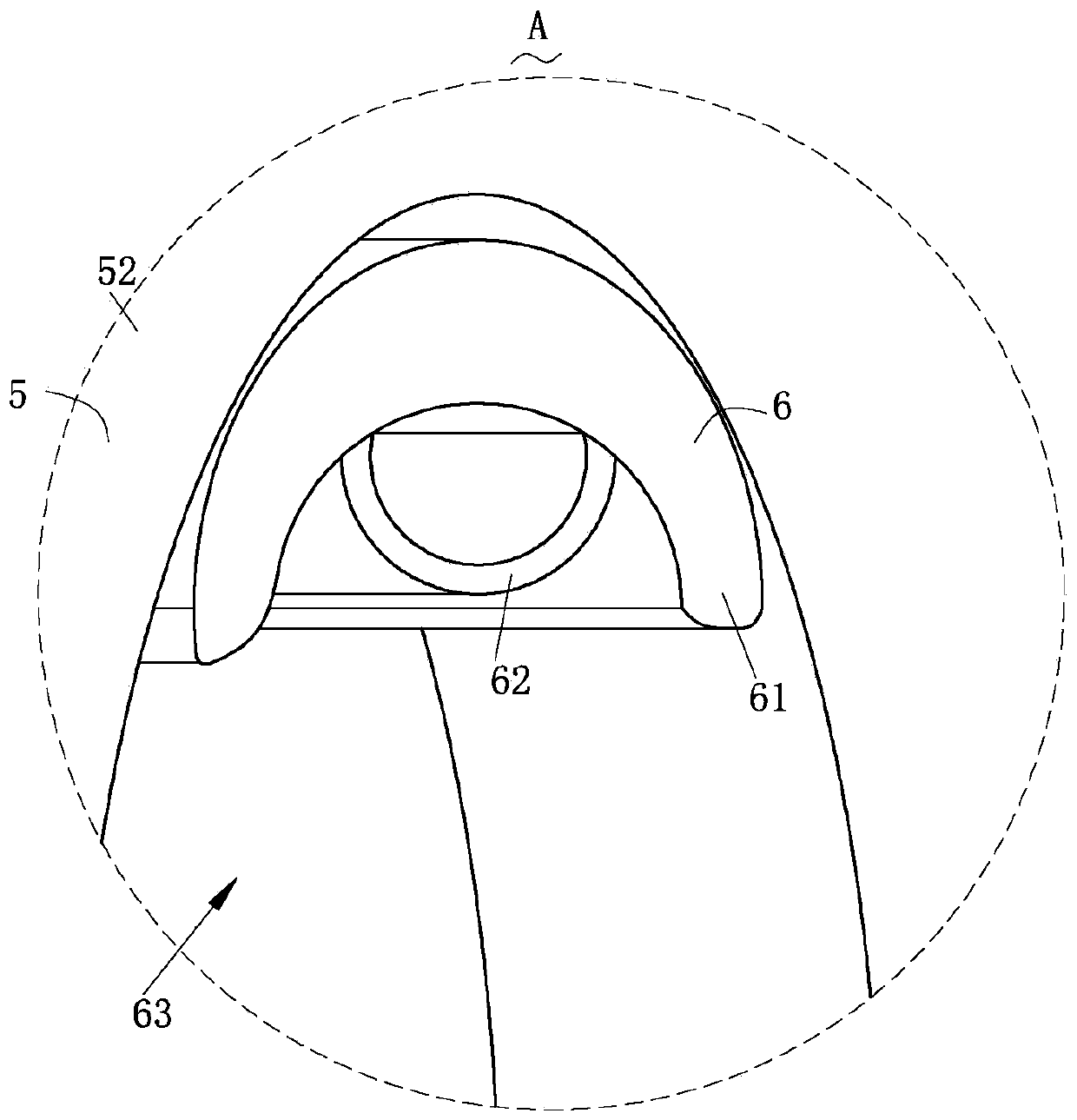
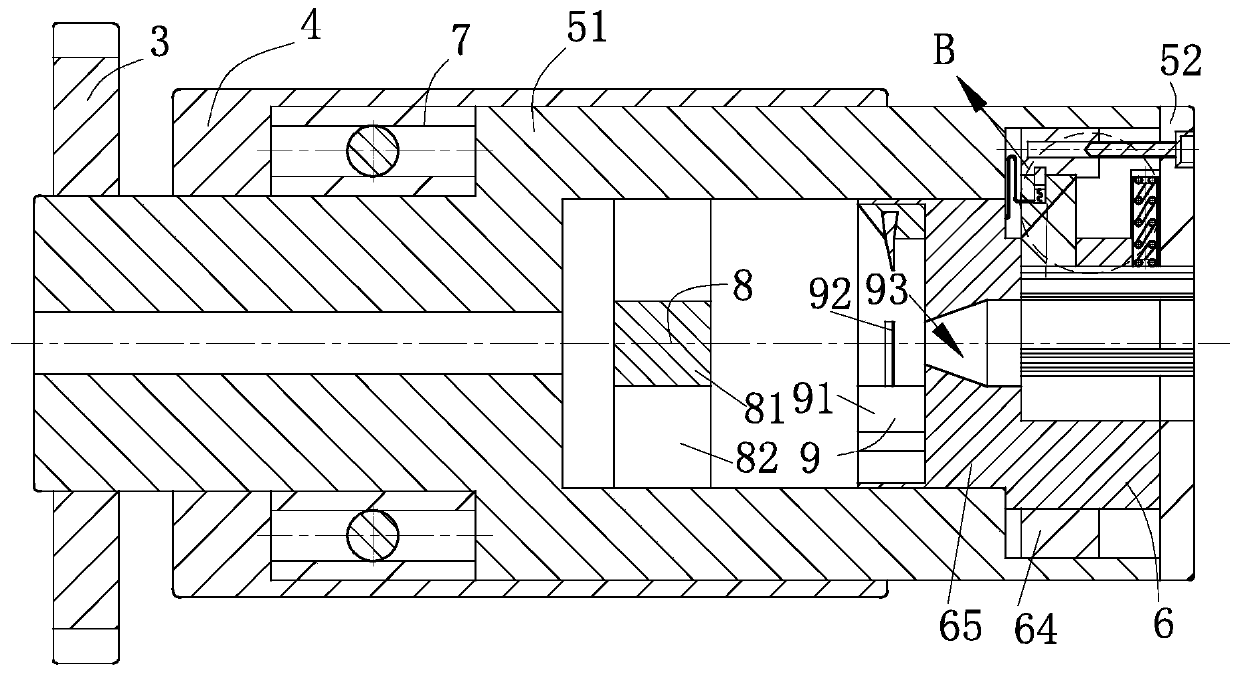
[0023] like Figure 1-Figure 6 As shown, a grease lubricated spindle according to the present invention includes a base 1, a rubber plug 2, a gear 3, a sleeve 4, a spindle structure 5, a clamping structure 6, a bearing 7, a dust removal structure 8 and a limit structure 9 ; The base 1 is fixed on the side wall of the sleeve 4 of the cylindrical structure; the main shaft structure 5 for transmission is connected to the sleeve 4 in rotation, and the inside of the sleeve 4 is provided with a The bearing 7 is guided, the base 1 is provided with the rubber plug 2 for sealing the grease hole, the rubber plug 2 is engaged with the base 1, and the main shaft structure 5 passes through The bearing 7 is rotationally connected to the sleeve 4, one end of th...


PUM


Abstract

The invention relates to the field of grease lubrication spindles, in particular to a grease lubrication spindle. The grease lubrication spindle comprises a base, a rubber plug, a gear, a sleeve, a spindle structure, a clamping structure, a bearing, a dust cleaning structure and a limiting structure. A driving ring and a stop block are fixed through the limiting structure. The driving ring is limited through centrifugal force generated during rotating of the spindle structure and the stable state of the limiting structure. When the spindle structure stops emergently, the limiting structure drives the driving ring to be separated from the stop block under the inertia effect so that the clamping structure cannot clamp a workpiece, the spindle structure can rotate continuously, and then the situation that a cutting tool and a motor of the cutting tool are damaged due to emergent stop of the spindle structure is effectively prevented. Through the dust cleaning structure, the limiting structure is more stable under the condition of normal rotation of the spindle structure. The limiting structure disperses air flow to effectively prevent the situation that cut scraps are splashed due toexcessive wind power caused by high-speed rotation of the spindle structure. Accordingly, the dust cleaning quality is greatly improved.

Description

technical field [0001] The invention relates to the field of grease lubricated spindles, in particular to a grease lubricated spindle. Background technique [0002] The main shaft refers to the shaft that receives power from the engine or motor and transmits it to other parts. The main shaft of the machine tool refers to the shaft that drives the workpiece or tool to rotate on the machine tool. It is usually composed of the main shaft, bearings and transmission parts (gears or pulleys). Spindle components are mainly used to support transmission parts such as gears and pulleys in machines to transmit motion and torque, such as machine tool spindles; some are used to clamp workpieces. [0003] However, when the main shaft in the lathe clamps workpieces with different sizes and cylindrical structures, it is easy to cause uneven force on the workpiece, resulting in deep indentations on the surface of the workpiece with poor hardness, and waste chips are easy to enter during the ...

Claims


Application Information

Patent Timeline
Patent Type & Authority Applications(China)
IPC IPC(8): B23B19/02B23Q11/12
CPCB23Q1/70B23Q11/12
Inventor 不公告发明人
Owner 安徽航睿电子科技有限公司
Learn More