A mechanical arm for handcart cargo loading and unloading
A technology of mechanical arms and trolleys, applied in the field of mechanical arms for loading and unloading goods with manual trolleys, can solve problems such as increased costs, increased handling time, and inapplicability to market demand, so as to avoid safety accidents, speed up loading and unloading efficiency, and liberate labor effect
- Summary
- Abstract
- Description
- Claims
- Application Information
AI Technical Summary
Problems solved by technology
Method used
Image

Examples
Embodiment Construction
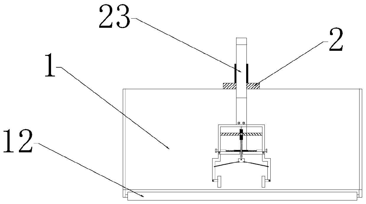
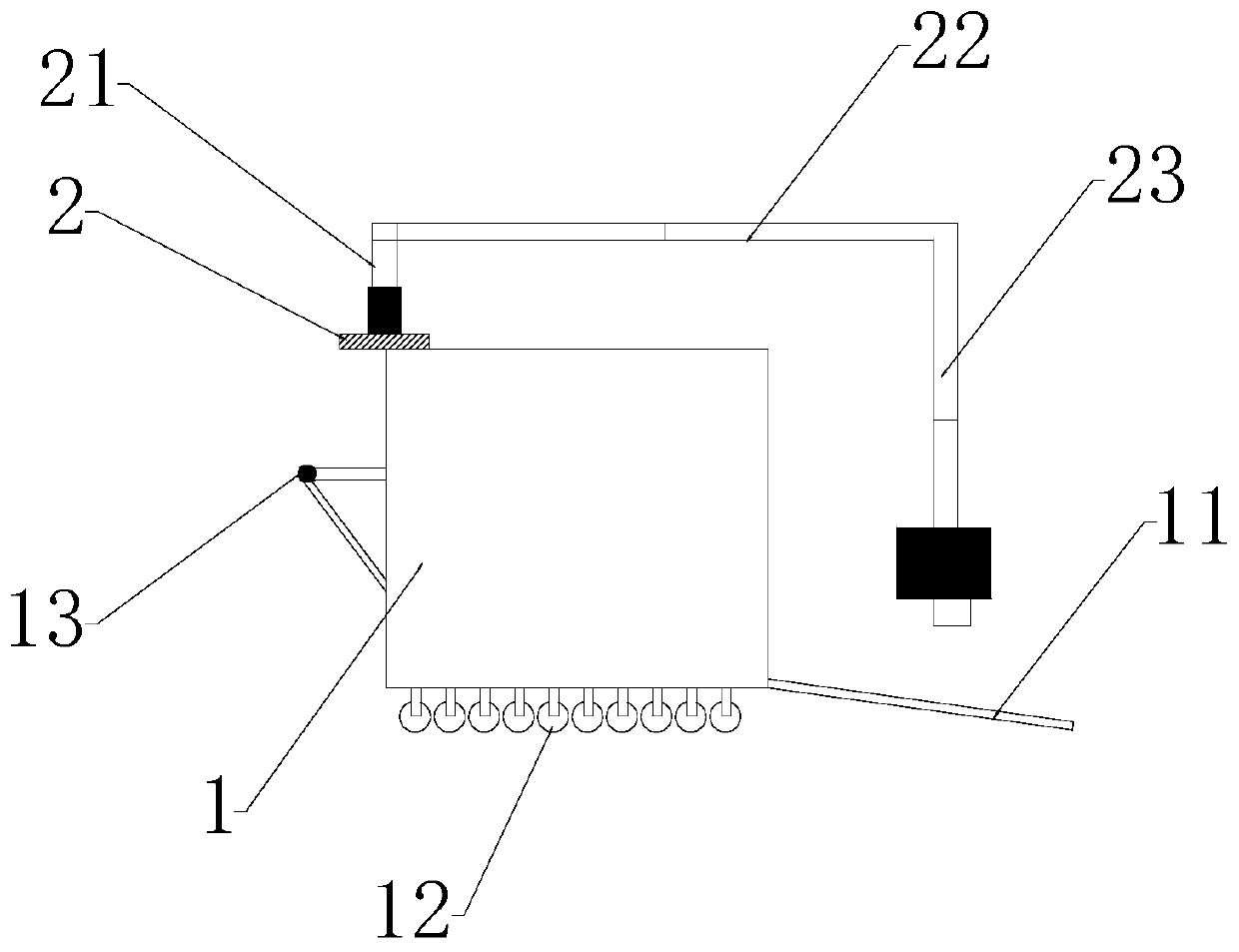
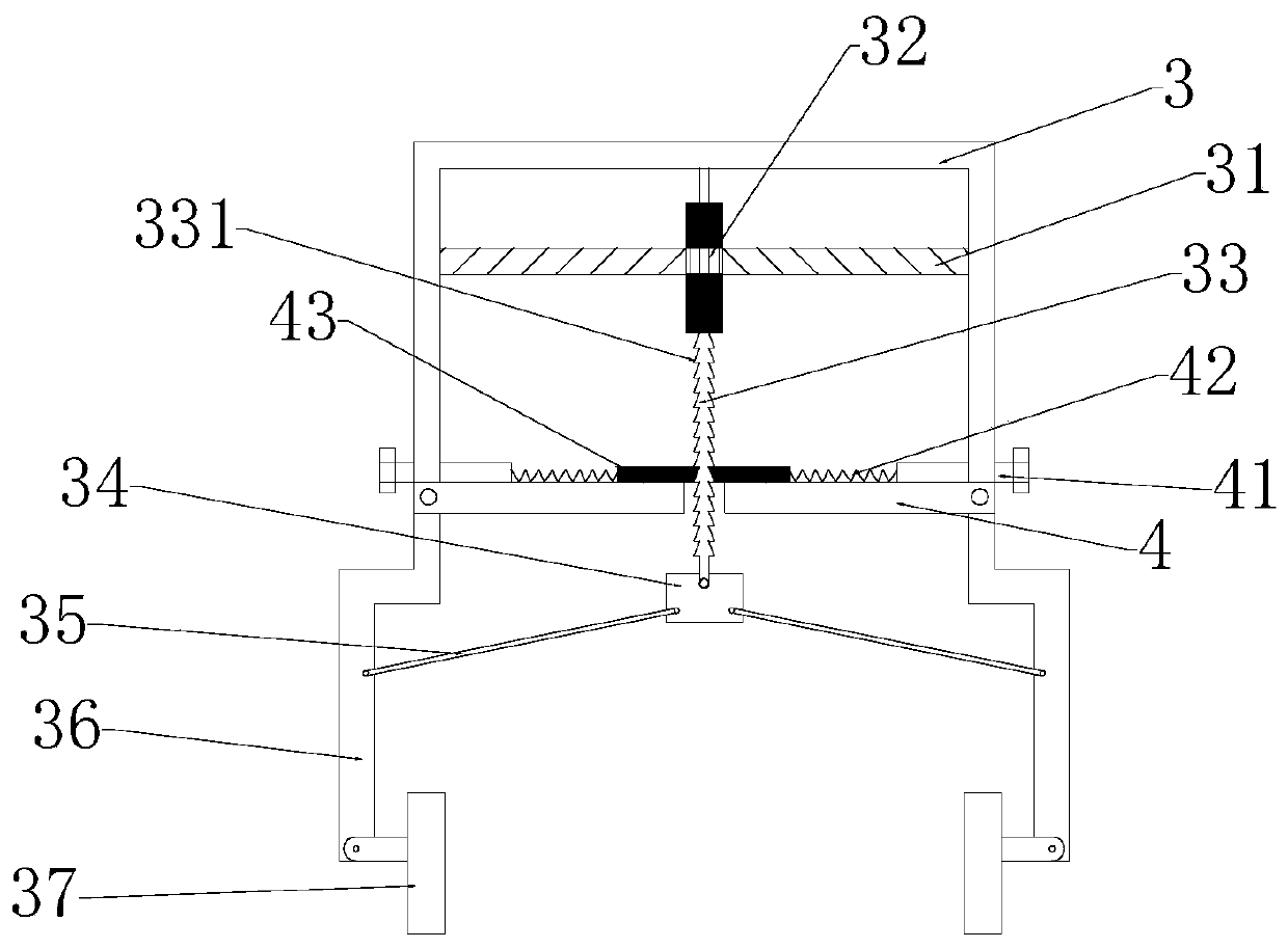
[0023] figure 1 It is a structural schematic diagram of the present invention, figure 2 for figure 1 side view, image 3 It is a schematic diagram of the clamping assembly of the present invention, Figure 4 It is a schematic diagram of the trolley body of the present invention, Figure 5 It is a combined schematic diagram of the anti-retraction block of the present invention, Figure 6 It is a schematic diagram of the separation of the anti-retraction block of the present invention. As shown in the figure, the mechanical arm for loading and unloading the manual trolley in this embodiment includes a trolley body 1, a mechanical arm assembly installed on the trolley body 1, and a mechanical arm assembly installed on the trolley body 1. The clamping assembly at the end and the auxiliary clamping assembly maintain a stable clamping safety assembly; the mechanical arm assembly includes an arm base 2 arranged on the trolley body 1 for installing a mechanical arm, and the mecha...
PUM
 Abstract
Description
Claims
Application Information
PatSnap Eureka turns technology decisions into work you can execute. Powered by our Innovation Knowledge Graph, it runs expert workflows across engineering, life sciences, materials and intellectual property. Get your review-ready output in minutes.


