
Urine collecting and cleaning system

A cleaning system and urine technology, applied in the field of urine collection and cleaning systems, can solve the problems of incomplete flushing, high cost, complicated operation, etc., and achieve the effect of convenient control, low cost and few parts

Inactive Publication Date: 2019-10-18
重庆德方信息技术有限公司
View PDF14 Cites 2 Cited by
  • Summary
  • Abstract
  • Description
  • Claims
  • Application Information

AI Technical Summary

Problems solved by technology

[0009] The present invention intends to provide a urine collection and cleaning system to solve the problems of high cost, complicated operation and incomplete flushing existing in the toilet with urine collection and urine flushing in the prior art

Method used


Image

  • Urine collecting and cleaning system
  • Urine collecting and cleaning system
  • Urine collecting and cleaning system

Examples


Embodiment 1

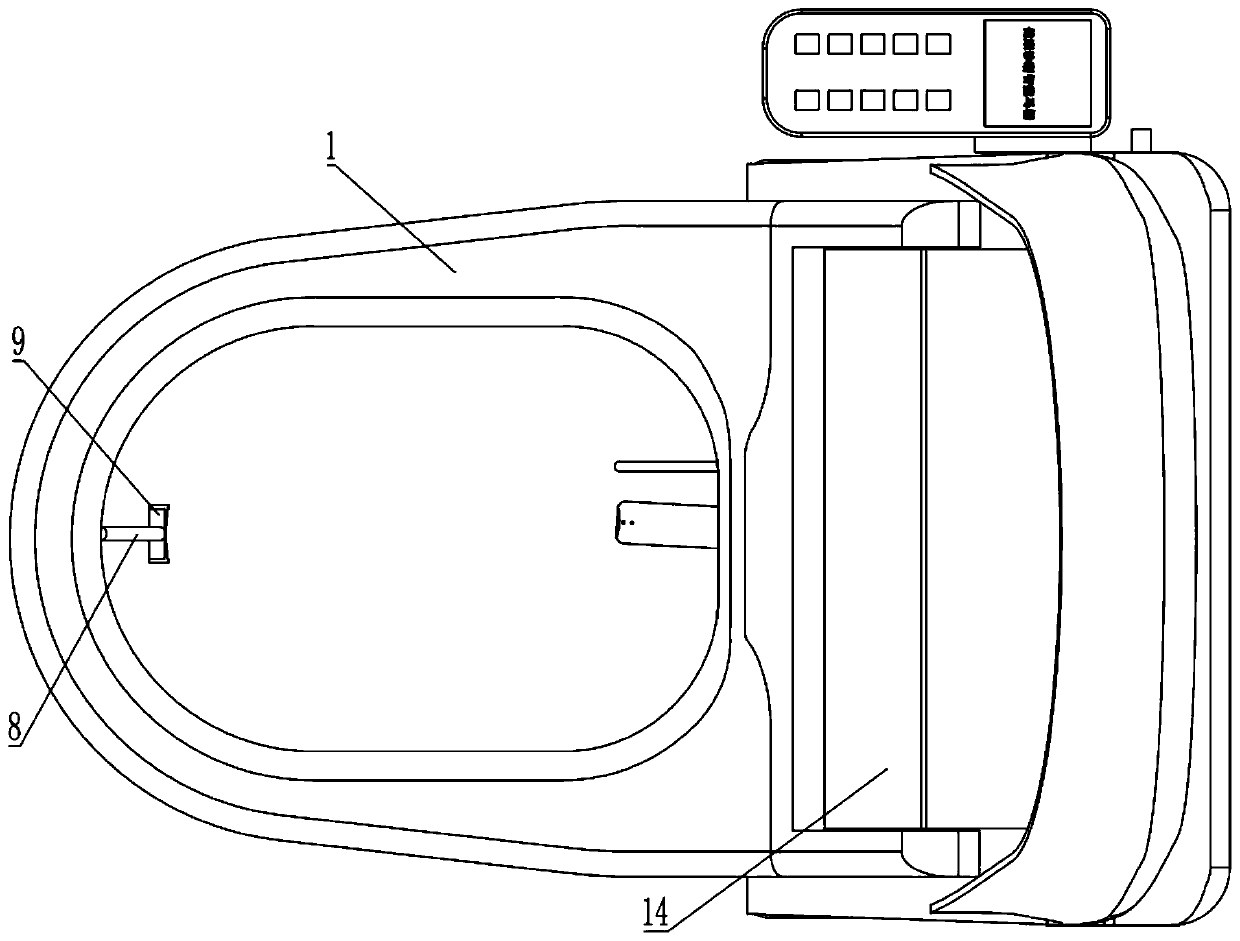
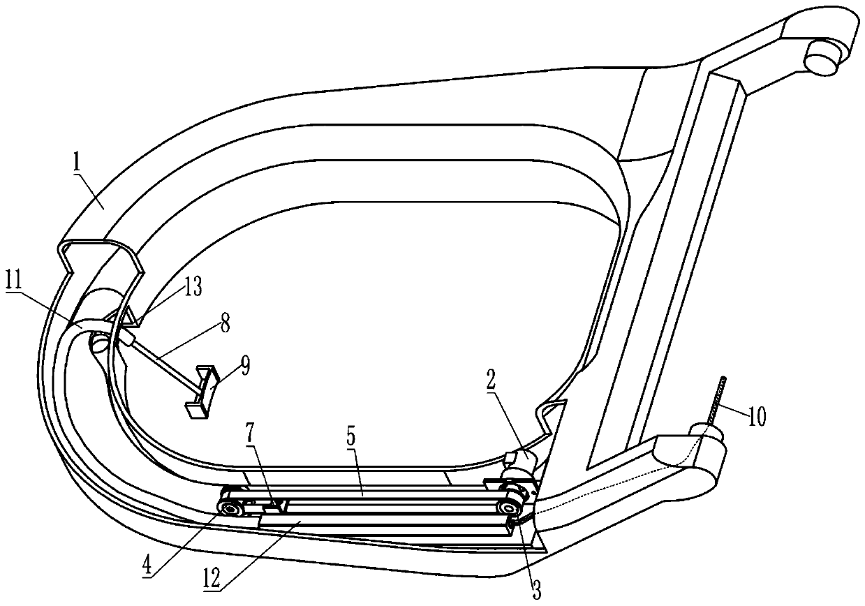
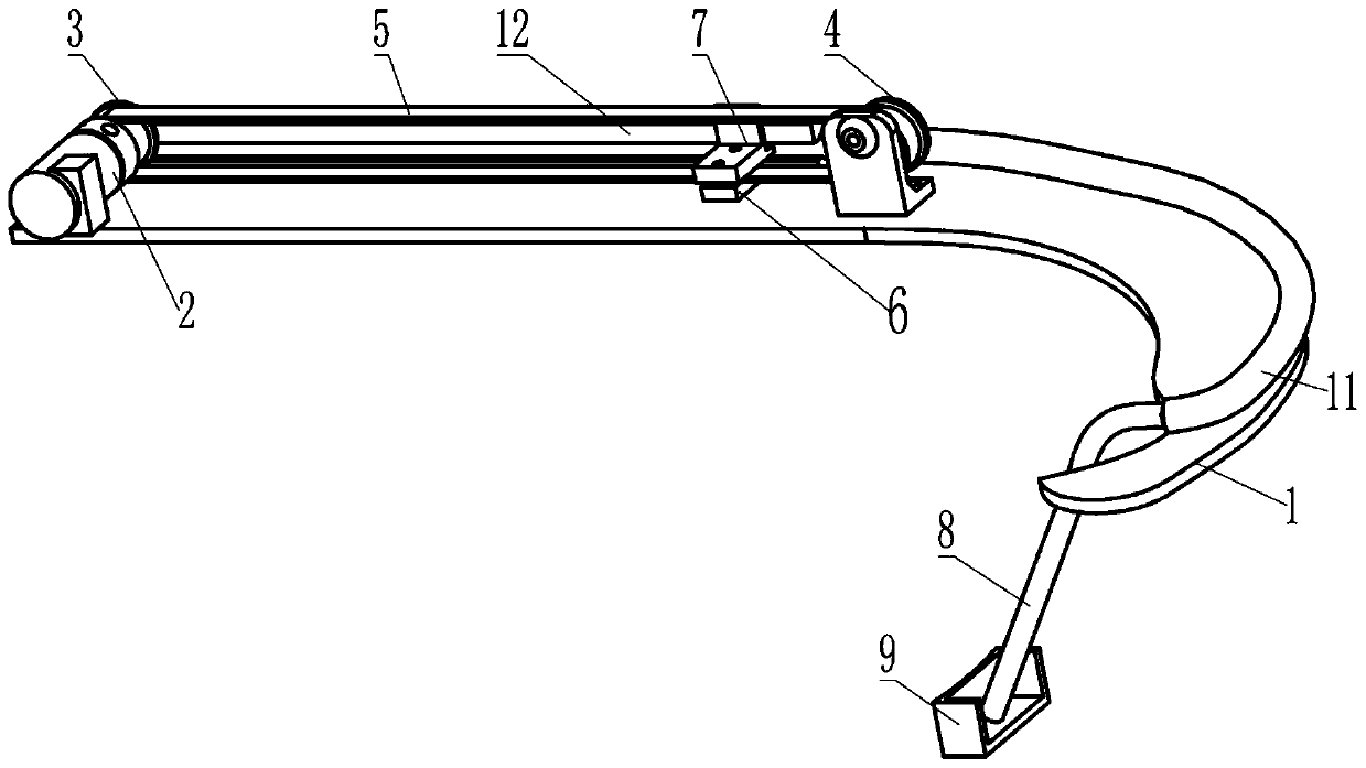
[0043] Embodiment one is basically as attached Figure 1 to Figure 5 Shown:

[0044] The urine collection and cleaning system includes a toilet lid seat 1 and a toilet lid base 14. The toilet lid seat 1 is connected with a collection box 9, a collection hose 10, a guide tube 11, a guide groove 12, a drive unit and a cleaning mechanism, and the toilet A solenoid valve, a peristaltic pump, a water diversion valve and a buffer pool are fixedly installed in the cover base 14 .

[0045] The water diversion valve is a water diversion valve with one inlet and three outlets. The water inlet of the water diversion valve is called the Z end (the water inlet is connected to the tap water interface of the toilet), and the three water outlets of the water diversion valve are called the H end and the N end respectively. end and D end.

[0046] combine figure 2 with Figure 5, the top of the buffer pool is provided with a flushing water port and an overflow port, the flushing water port...

Embodiment 2

[0063] combine Image 6 , Embodiment 2 is improved on the basis of Embodiment 1, and the improvements are as follows: the toilet seat 1 is connected with a reset sensor 15 by screws, the reset sensor 15 is externally connected with a controller, and the controller is electrically connected with a motor driver, and the motor The driver is used to open and close the acquisition motor 2, and the connection block 7 can touch the reset sensor 15 when it moves to the far right, and then trigger the reset sensor 15; the controller adopts a single-chip microcomputer model STM32F407.

[0064] The specific implementation process is as follows:

[0065] In this embodiment 2, an improvement is made on the third step "cleaning the outside of the pipeline" in the urine cleaning process of the first embodiment. In this embodiment 2, the specific process of cleaning the outside of the pipeline in the third step of urine cleaning is as follows:

[0066] After the internal cleaning of the pipe...


PUM


Abstract

The invention relates to the technical field of sanitary and bathroom equipment, and particularly discloses an urine collecting and cleaning system. The urine collecting and cleaning system comprisesa toilet lid seat ring, a toilet lid base, a negative pressure unit, a buffering pool, a cleaning mechanism and a shunt valve, wherein the toilet lid seat ring is connected with a collecting hose; thecollecting hose is fixedly connected with a collecting box; one end of the negative pressure unit is communicated with the collecting hose, and the other end of the negative pressure unit is communicated with the buffering pool; the cleaning mechanism comprises a cleaning pipe and a cleaning spray nozzle; the cleaning pipe is communicated with the cleaning spray nozzle; the cleaning spray nozzlefaces one end of the collecting hose, which is connected with a collecting box; a water inlet of the shunt valve is connected with an external water supply unit; and a plurality of bleeders of the shunt valve are respectively connected with the cleaning pipe and the buffering pool. According to the scheme, by arranging the negative pressure unit, the buffering pool, the cleaning mechanism and theshunt valve, problems of high cost, complex operation and incomplete flushing of a toilet with urine collecting and urine flushing functions in the prior art are solved.

Description

technical field [0001] The invention relates to the technical field of bathroom equipment, in particular to a urine collection and cleaning system. Background technique [0002] Everyone goes to the toilet to urinate every day. The status of urination can directly reflect the health status of many bodies, including the presence of urinary system diseases, liver and gallbladder diseases, diabetes and other diseases. Urine detection is of great significance for early detection of these diseases and health status assessment. effect. [0003] However, at present, a urine test usually requires a professional examination in a hospital, which will consume a lot of time and energy, and is especially difficult for the elderly with inconvenient mobility; and before the urine test, it is necessary to collect urine. Most of the methods are manual collection, that is, the person to be collected urinates into the urine collection cup. This kind of collection method is inconvenient for so...

Claims


Application Information

Patent Timeline
Patent Type & Authority Applications(China)
IPC IPC(8): G01N1/14A61B10/00B08B9/023B08B9/032B08B9/08B08B9/093A47K13/14A47K13/24
CPCG01N1/14A61B10/007B08B9/023B08B9/032B08B9/08B08B9/093A47K13/14A47K13/24G01N2001/1427
Inventor 李春林
Owner 重庆德方信息技术有限公司
Learn More