Electrical connector terminal

A technology for electrical connectors and terminals, applied in the direction of contact parts, etc., can solve problems such as affecting the smooth insertion and pollution of plug-in components, and achieve the effect of eliminating the gel phenomenon and improving convenience.

Pending Publication Date: 2019-10-18
GOLDENCONN ELECTRONICS TECH CO LTD
View PDF0 Cites 1 Cited by
  • Summary
  • Abstract
  • Description
  • Claims
  • Application Information

AI Technical Summary

Problems solved by technology

In the process of injection molding, when the injection pressure is not selected properly, the liquid plastic can easily enter the conductive core insertion part along the welding part of the electrical connector terminal, thereby forming a gel on the elastic contact arm, thereby polluting it , which in turn affects the smooth insertion of the matching plug-in components

Method used


Image

  • Electrical connector terminal
  • Electrical connector terminal
  • Electrical connector terminal

Examples


Embodiment Construction

[0021] In the description of the present invention, it should be understood that the orientations or positional relationships indicated by the terms "left", "right", "front", "rear" etc. are based on the orientations or positional relationships shown in the drawings, and are only for It is convenient to describe the present invention and simplify the description, but does not indicate or imply that the device or element referred to must have a specific orientation, be constructed and operate in a specific orientation, and thus should not be construed as limiting the present invention.

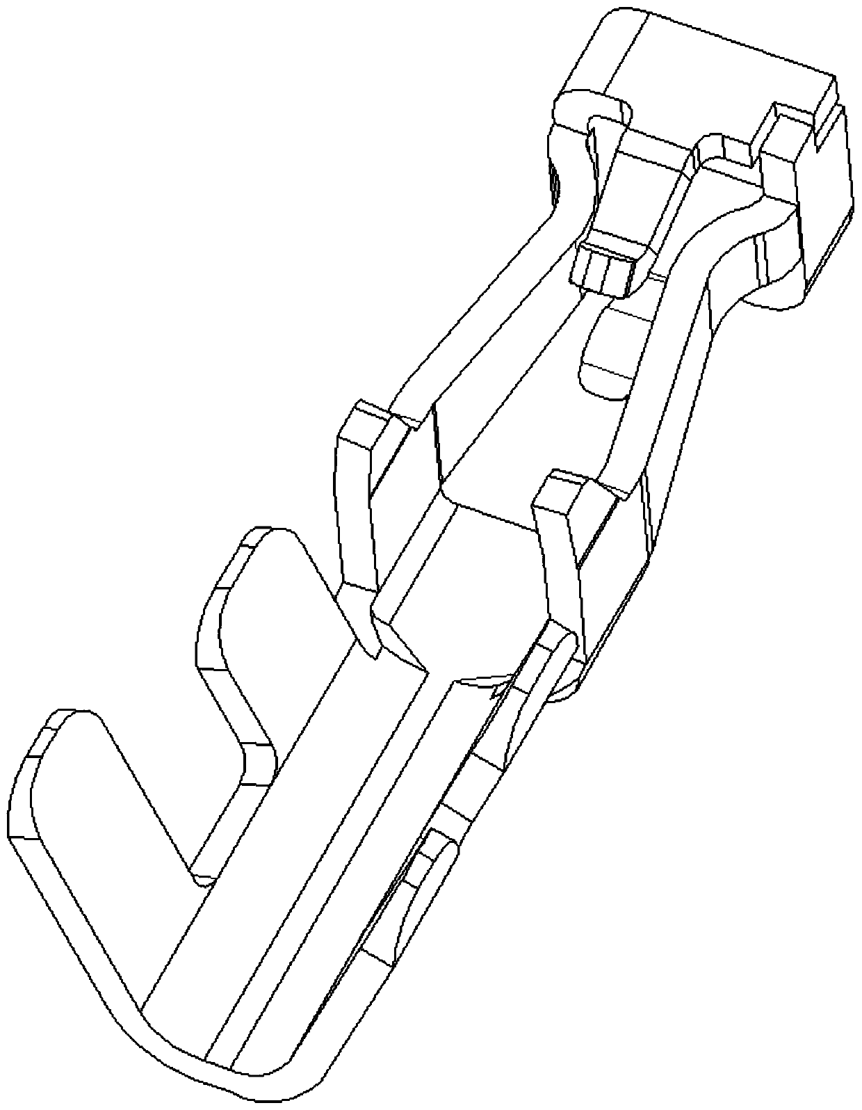
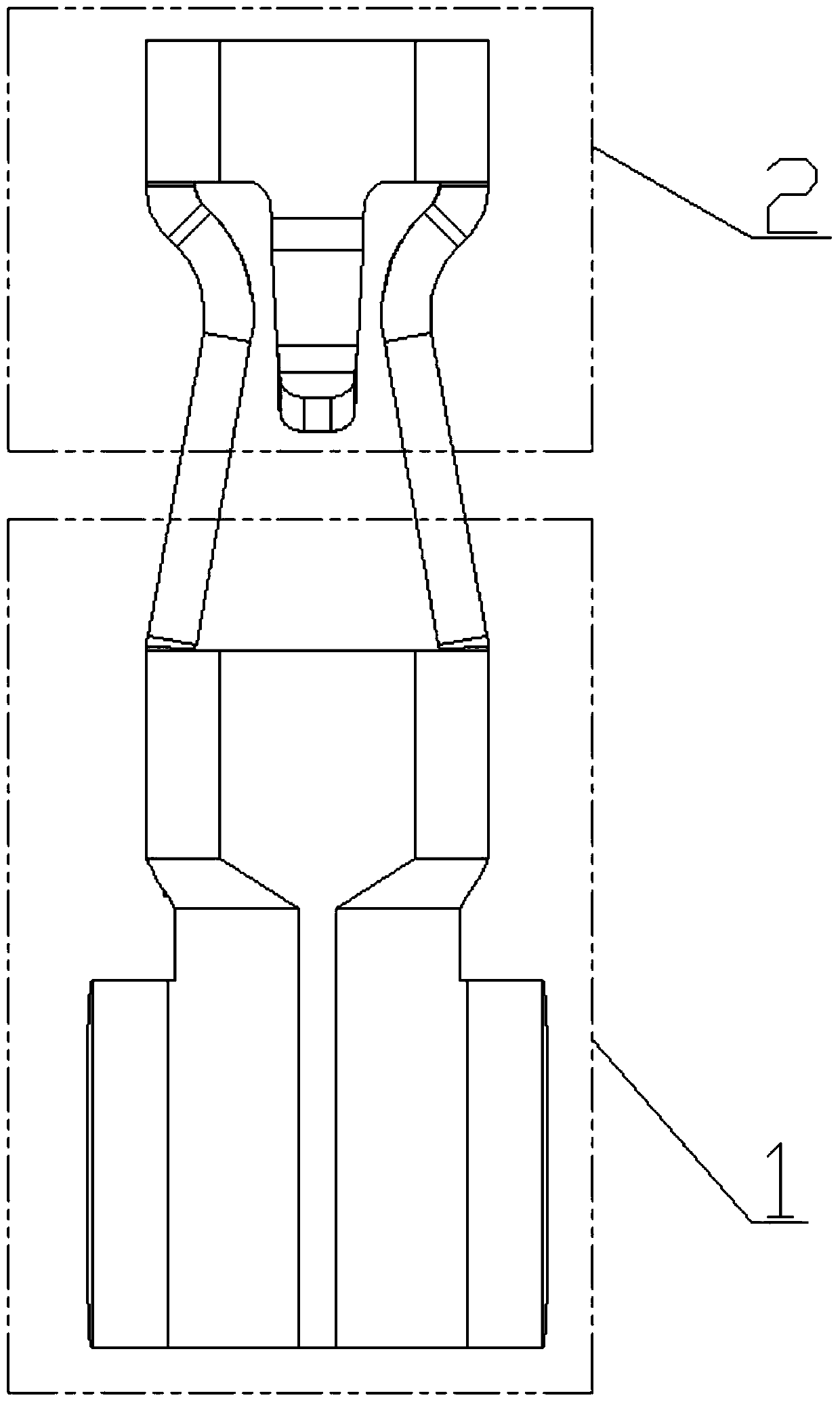
[0022] Below in conjunction with specific embodiment, content of the present invention is described in further detail, image 3 , Figure 4 , Figure 5 The top view, left side view and perspective view of the electrical connector terminal in the present invention are respectively shown, which are formed by punching and bending a sheet metal body, which is composed of two parts: welding part 1 ...


PUM


Abstract

The invention relates to an electric connector terminal. A sheet-shaped metal body is punched and bent so as to form the electric connector terminal. The electric connector terminal is composed of a welding portion and a conductive insert core inserting portion. The cross section of the welding portion is U-shaped and is arranged along a direction away from the conductive insert core inserting portion; the welding portion comprises a first wire pressing area and a second wire pressing area which are connected in sequence; the left side and right side of the first wire pressing area are respectively provided with a left pressing wire elastic sheet and a right pressing wire elastic sheet; and the first wire pressing area comprises an adhesive stopping plate which is transversely placed in the cavity of the first wire pressing area. In this way, the adhesive stopping plate can effectively prevent liquid plastic from entering the conductive insert core inserting portion along the welding portion in an injection molding process, and therefore, adhesive solidification occurring on an elastic contact arm is avoided. In addition, the adhesive stopping plate can be used for limiting the insertion length of a conductive insert core, so that the convenience and consistency of construction are improved.

Description

technical field [0001] The invention relates to the technical field of electrical connector manufacturing, in particular to an electrical connector terminal. Background technique [0002] With the development of science and technology and the improvement of living standards, people's demand for electronic products is increasingly strong. Electrical connectors are widely used in power systems, communication networks, financial manufacturing, elevators, industrial automation, medical equipment, office equipment, home appliances, military manufacturing, automotive and other industries. They are mainly used to connect electronic products or between components in electronic products signal transmission. In the actual production process, after the welding work of the cable conductive core and the electrical connector terminal is completed, the whole is put into the rubber core, and then the wire cover is used to fit, and then put into the mold for injection molding process to for...

Claims


Application Information

Patent Timeline
Patent Type & Authority Applications(China)
IPC IPC(8): H01R13/02
CPCH01R13/02
Inventor 陈进嵩
Owner GOLDENCONN ELECTRONICS TECH CO LTD
Why Eureka
Try Eureka