Soil straw mixing agitator, spiral conveying unit and mixing agitation method

A technology of transmission unit and mixer, which is applied in the field of agricultural machinery and fertilizer returning to the field, which can solve the problems of affecting the quality of sowing operations and excessive straw, so as to improve the efficiency of returning to the field and ensure the emergence rate

Inactive Publication Date: 2019-10-22
HARBIN CITY ACAD OF AGRI SCI
View PDF5 Cites 2 Cited by
  • Summary
  • Abstract
  • Description
  • Claims
  • Application Information

AI Technical Summary

Problems solved by technology

[0006] In view of the above problems, the present invention discloses a soil straw mixing mixer, a spiral transmission unit and a mixing and mixing method, which can solve the problem that the quality of sowing operation is affected by too much local straw in the soil layer

Method used


Image

  • Soil straw mixing agitator, spiral conveying unit and mixing agitation method
  • Soil straw mixing agitator, spiral conveying unit and mixing agitation method
  • Soil straw mixing agitator, spiral conveying unit and mixing agitation method

Examples


specific Embodiment approach 1

[0036] This embodiment is the embodiment of the soil straw mixing mixer.

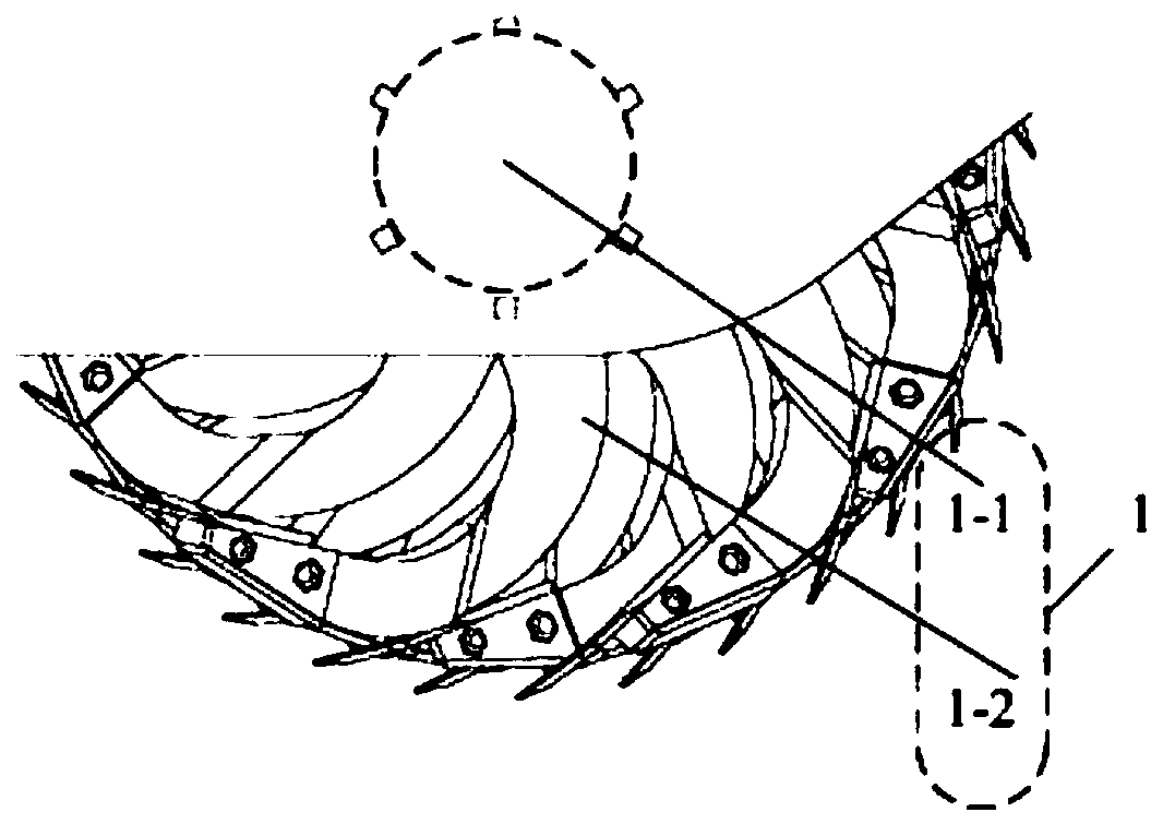
[0037] The soil straw mixing mixer under the present embodiment, the drawing is as follows figure 1 As shown; the soil straw mixing mixer is provided with a deep rotary mixing broken soil unit 1 and a spiral transmission unit 2 sequentially from front to back along the forward direction of the soil straw mixing mixer;

[0038] The deep rotary mixing unit 1 includes a first rotating shaft 1-1 and a deep rotary blade 1-2 evenly distributed on the first rotating shaft 1-1, such as figure 2 shown;

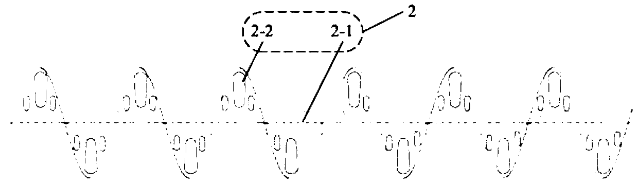
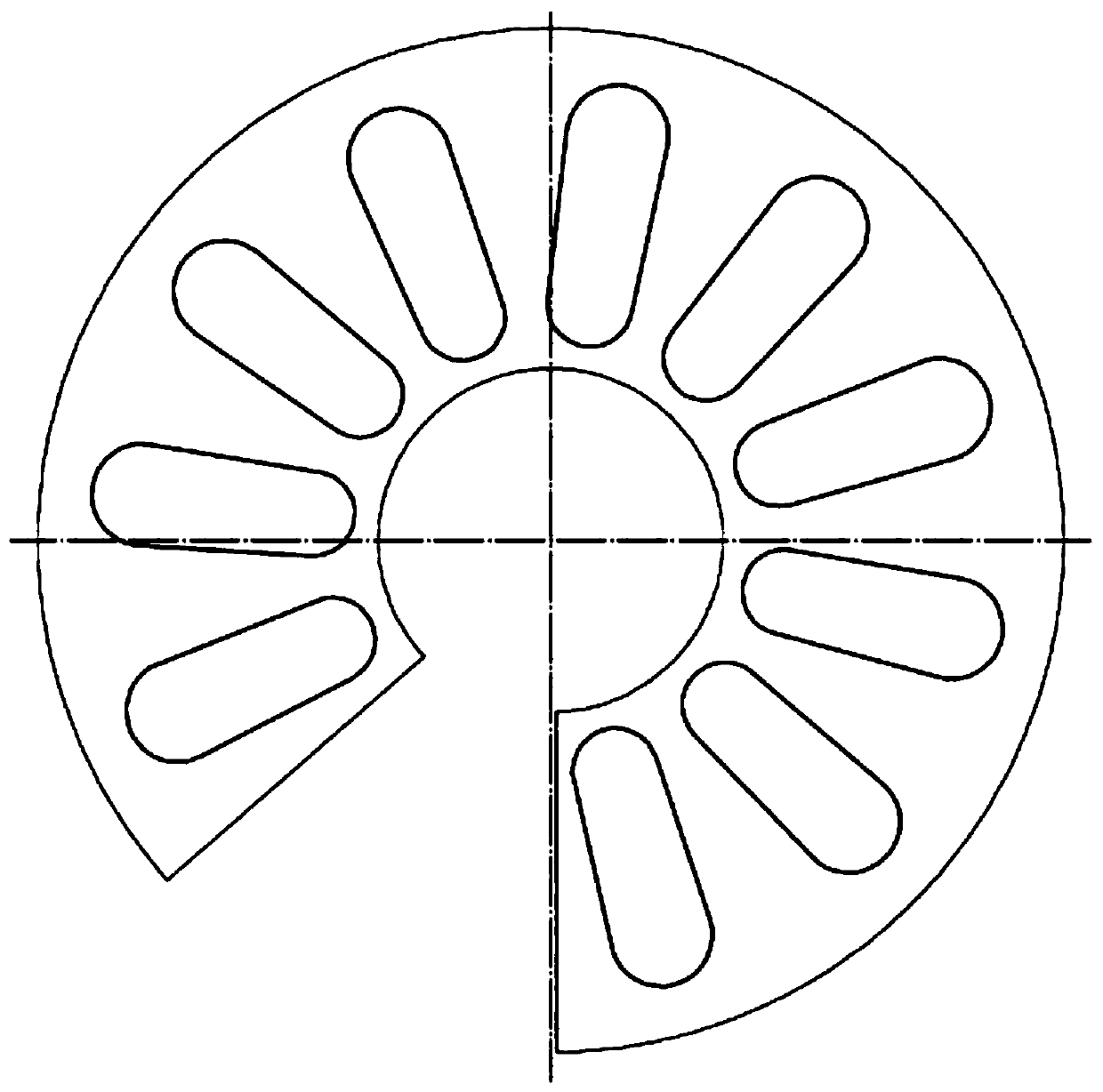
[0039] The screw transmission unit 2 includes a second rotating shaft 2-1 and two spiral blades 2-2 symmetrically distributed on the second rotating shaft 2-1, such as image 3 As shown; the helical directions of the two helical blades 2-2 are opposite, and long holes are evenly distributed on the helical blades 2-2, and the schematic diagram after the helical blades 2-2 is expanded is as follows Figure 4 A...

specific Embodiment approach 2

[0045] This embodiment is the embodiment of the screw transmission unit in the soil straw mixing mixer.

[0046] A spiral transmission unit capable of realizing secondary mixing of straw and soil, comprising a second rotating shaft 2-1 and two spiral blades 2-2 symmetrically distributed on the second rotating shaft 2-1, two spiral blades 2-2 The helical direction is opposite, and the helical blade 2-2 is evenly distributed with long holes.

specific Embodiment approach 3

[0048] This embodiment is an embodiment of the soil straw mixing and stirring method.

[0049] A method for mixing and stirring soil straw, comprising the following steps:

[0050] Step a, opening a trench for mixing soil and straw;

[0051]Step b, placing the soil straw mixing mixer on the groove, so that the groove is located in the middle of the soil straw mixing mixer;

[0052] Step c, moving the soil straw mixing mixer along the direction of the groove, specifically, moving from the screw conveying unit 2 to the direction of the deep rotary mixing crushed soil unit 1 .


PUM


Abstract

The invention discloses a soil straw mixing agitator, a spiral conveying unit and a mixing agitation method, and belongs to the technical field of agricultural machinery and fertilizer returning to the field. According to the soil straw mixing agitator, a deep rotation mixing and soil breaking unit and the spiral conveying unit are sequentially arranged from front to back along the advancing direction of the soil straw mixing agitator; the deep rotation mixing and soil breaking unit comprises a first rotation shaft and deep rotation scoops uniformly distributed on the first rotation shaft; thespiral conveying unit comprises a second rotation shaft and two spiral blades symmetrically distributed on the second rotation shaft, the two spiral blades are opposite in spiral directions, and slotholes are uniformly distributed on the spiral blades; the second rotation shaft reversely rotates when the soil straw mixing agitator advances. The idea of pushing straws from a ground surface to anunderground space into grooves and burying the straws is put forward, the mixing agitator and the spiral conveying unit for implementing the scheme are designed, and the problem of the influence of excessive local straws in a soil layer on seeding operation quality is solved.

Description

technical field [0001] The invention relates to a soil straw mixing mixer, a screw transmission unit and a mixing and mixing method, which belong to the technical field of agricultural machinery and fertilizer returning to field. Background technique [0002] Since the 1980s, with the substantial increase in my country's grain production, the amount of straw has also increased significantly; coupled with the popularization and application of central heating and liquefied petroleum gas, a large amount of straw has begun to remain in rural areas. If the straw is thrown directly on the ground to decompose naturally, the planting of the next season's crops will be affected due to the limited decomposition speed. It can be seen that how to deal with the remaining straw has become an urgent problem to be solved in agricultural production. [0003] Due to the huge amount of remaining straw, the high transportation cost and the inability of livestock to eat it all, straw burning ha...

Claims


Application Information

Patent Timeline
Patent Type & Authority Applications(China)
IPC IPC(8): A01B33/02A01B33/08A01B33/10A01B33/12A01B79/00
CPCA01B33/024A01B33/082A01B33/10A01B33/12A01B79/00
Inventor 毕春辉陈长海杨沫李明畅王明军张宁金钟玉
Owner HARBIN CITY ACAD OF AGRI SCI
Why Eureka
Try Eureka