Preparation system for waterproof paint
A technology for preparing systems and waterproof coatings, applied in the direction of dissolution, mixers, chemical instruments and methods, etc., can solve the problems of poor stirring and mixing effects, ingredients that cannot be uniformly dispersed and mixed together, etc., to achieve good mixing effects and high-quality products High, easy to mix and stir effect
- Summary
- Abstract
- Description
- Claims
- Application Information
AI Technical Summary
Problems solved by technology
Method used
Image

Examples
specific Embodiment approach 1
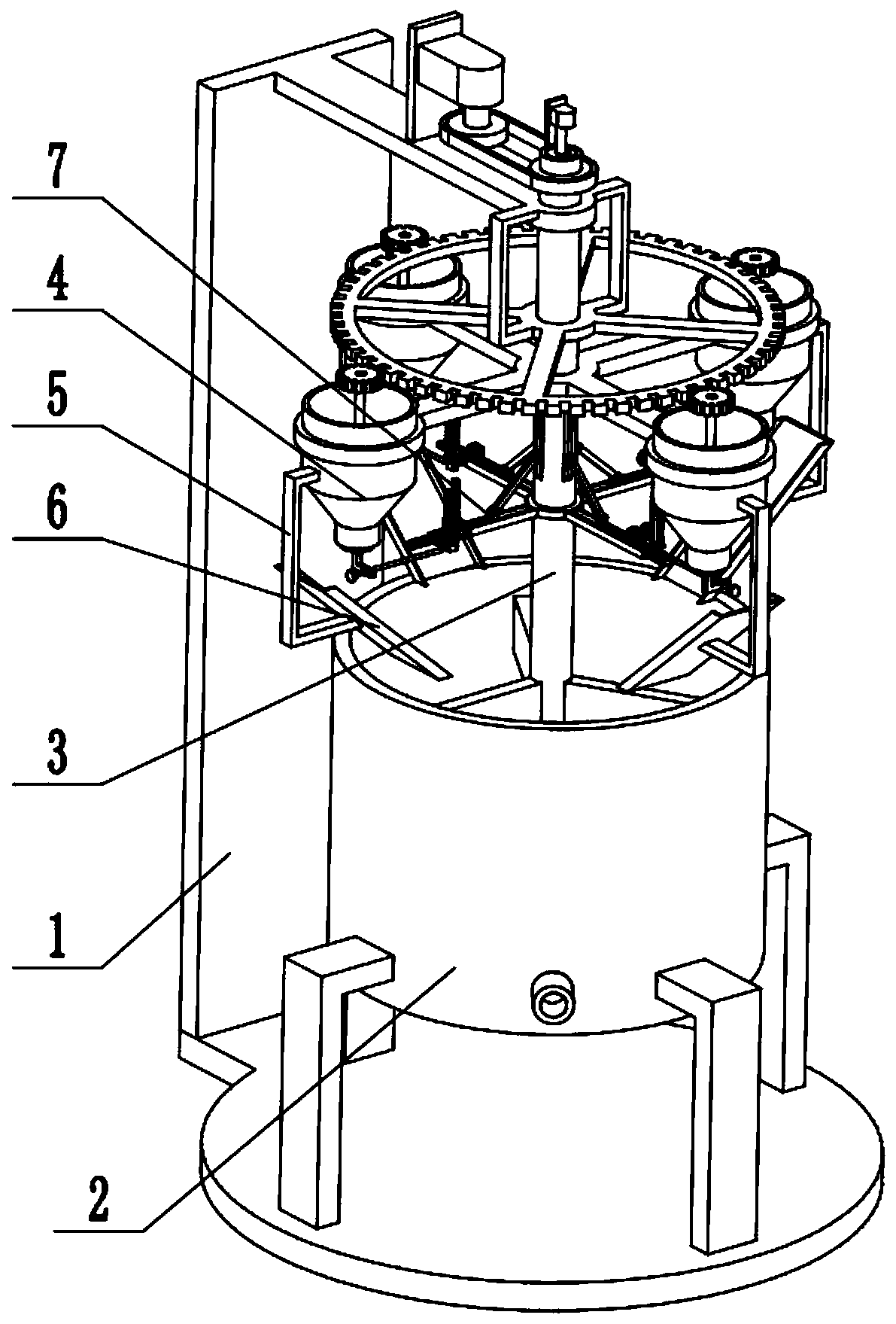
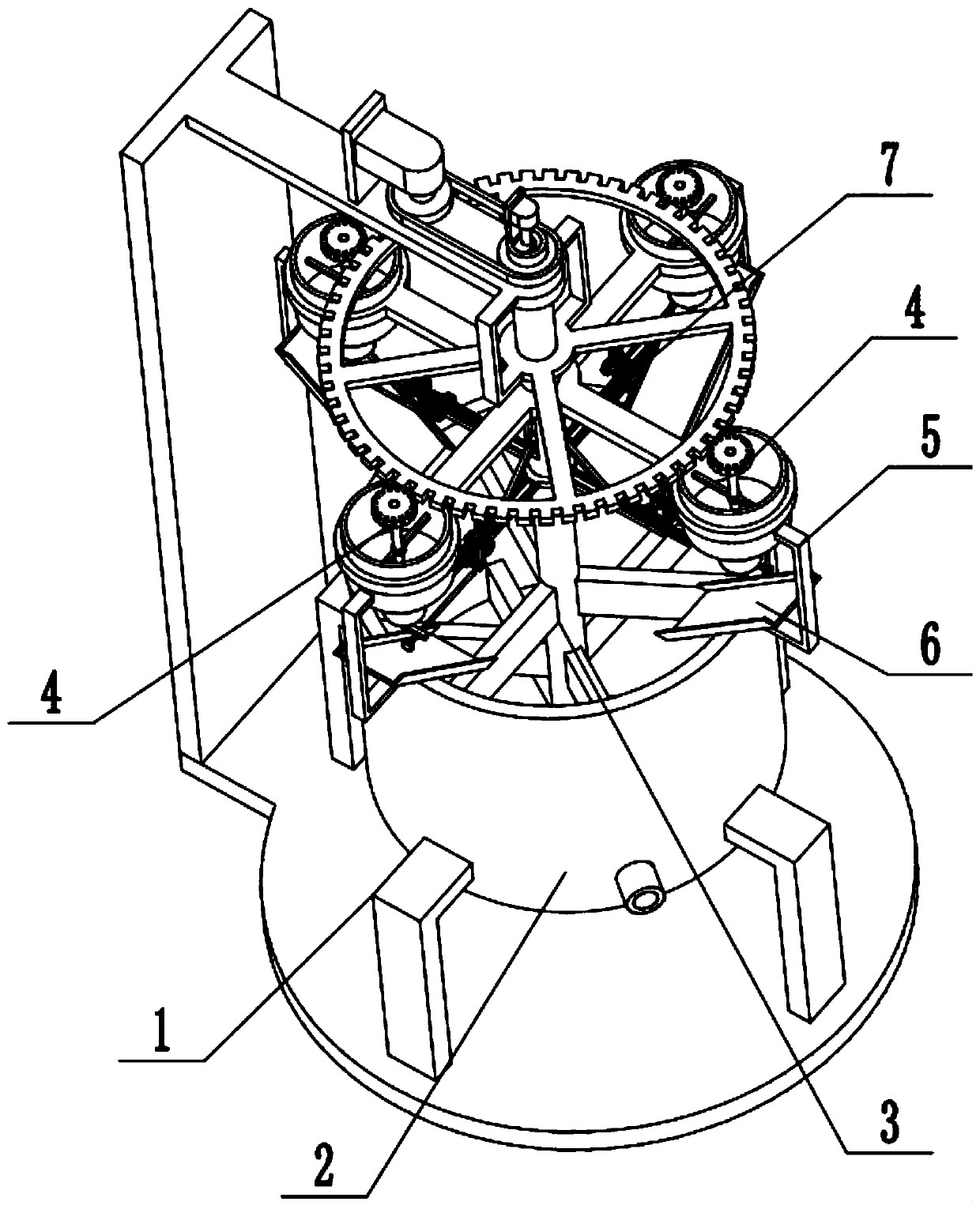
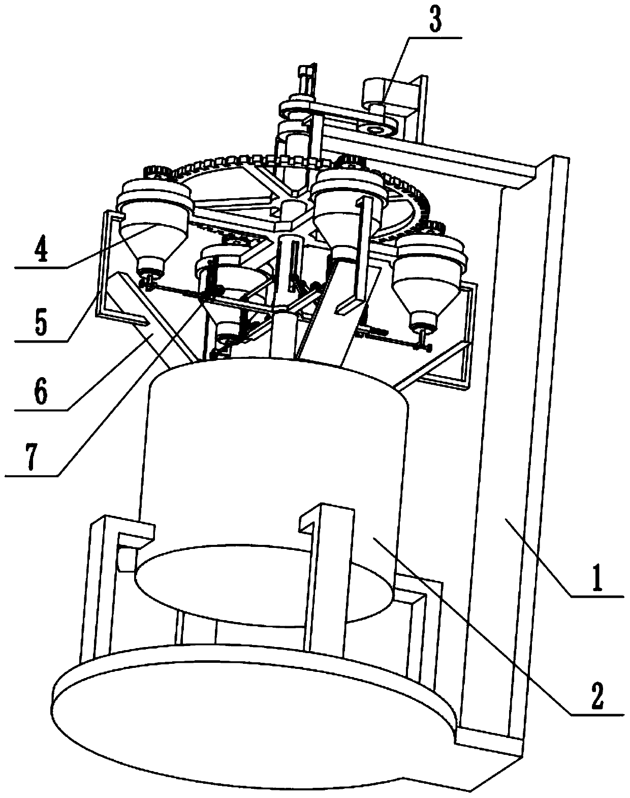
[0029] Combine below Figure 1-12Describe this embodiment, a waterproof paint preparation system, including a frame 1, a mixing drum 2, a stirring device 3, a feeding drum assembly 4, a connecting arm 5, a feeding swash plate 6 and a feeding linkage control mechanism 7, the mixing The mixing drum 2 is fixedly connected to the frame 1, the lower end of the mixing drum 2 is provided with a drain pipe with a control valve, the upper end of the stirring device 3 is set on the frame 1, and the lower end of the mixing device 3 is located Inside, there are four feeding tube assemblies 4, and the four feeding tube assemblies 4 are evenly arranged on the stirring device 3, and the four feeding tube assemblies 4 are all located above the mixing drum 2, and the four feeding tube assemblies 4 are all connected to the machine. The frame 1 is connected by transmission, and the four feeding cylinder assemblies 4 are all fixedly connected to a feeding swash plate 6 through the connecting arm ...
specific Embodiment approach 2
[0031] Combine below Figure 1-12 To illustrate this embodiment, the frame 1 includes a base 1-1, a support foot 1-2, a vertical support plate 1-3, a pedestal plate 1-4, a C-shaped frame 1-5, and an outer ring gear 1-6 The base 1-1 is uniformly surrounded and fixedly connected to four supporting feet 1-2, the mixing drum 2 is fixedly connected to the four supporting feet 1-2, and the upper and lower ends of the vertical supporting plate 1-3 are respectively fixedly connected to the shaft frame plate 1-4 and the rear end of the base 1-1, the outer ring gear 1-6 is fixedly connected to the lower end of the front end of the axle frame plate 1-4 through two C-shaped frames 1-5, and the outer ring gear 1-6 is connected to four feeding The barrel assembly 4 is connected by transmission, and the outer ring gear 1-6 is connected to the stirring device 3 with clearance fit.
specific Embodiment approach 3
[0033] Combine below Figure 1-12 To illustrate this embodiment, the stirring device 3 includes a motor I 3-1, a driving pulley 3-2, a driven pulley 3-3, a central shaft 3-4, a cross 3-5, a fixed ring 3-6, a vertical The chute 3-7 and the mixing blade 3-8; the motor I3-1 is fixedly connected to the shaft frame plate 1-4 through the motor frame, the output shaft of the motor I3-1 is fixedly connected to the driving pulley 3-2, and the driving pulley 3 -2 is connected with the driven pulley 3-3 through a belt drive, the driven pulley 3-3 is fixedly connected to the upper end of the central shaft 3-4, and the central shaft 3-4 is connected to the axle frame plate 1 through a bearing with a seat for rotation On -4, four vertical chutes 3-7 are evenly set around the middle of the central axis 3-4, the cross 3-5 is fixedly connected to the central axis 3-4, and the cross 3-5 is located above the vertical chute 3-7 , the four fixed rings 3-6 are uniformly surrounded and fixedly conn...
PUM
 Abstract
Description
Claims
Application Information
 - R&D
- Intellectual Property
- Life Sciences
- Materials
- Tech Scout
- Unparalleled Data Quality
- Higher Quality Content
- 60% Fewer Hallucinations
Browse by: Latest US Patents, China's latest patents, Technical Efficacy Thesaurus, Application Domain, Technology Topic, Popular Technical Reports.
© 2025 PatSnap. All rights reserved.Legal|Privacy policy|Modern Slavery Act Transparency Statement|Sitemap|About US| Contact US: help@patsnap.com