Punching machining die device based on special-shaped seamless steel pipe arc section blanking and pressing

A technology for processing seamless steel pipes and molds, which is applied to metal processing equipment, perforating tools, manufacturing tools, etc., and can solve problems such as lengthening of special-shaped pipes, thick die pads, and affecting the quality of molded parts.

Active Publication Date: 2019-10-22
西安美汉电气工程有限公司
View PDF5 Cites 6 Cited by
  • Summary
  • Abstract
  • Description
  • Claims
  • Application Information

AI Technical Summary

Problems solved by technology

[0004] Aiming at the deficiencies in the prior art, the purpose of the present invention is to provide a punching processing die equipment based on the cutting and pressing of the arc section of the special-shaped seamless steel pipe to solve the problem that the aluminum curved surface of the aluminum alloy special-shaped steel pipe has a large tension, so as to cooperate with the punching operation. In the bending die, the pressing and pasting of the covering surface will be formed. After the punching is completed, the aluminum cutting surface will be missed and pressed in the corner slot of the bending die, causing the sharp aluminum surface cracks to scratch the b

Method used


Image

  • Punching machining die device based on special-shaped seamless steel pipe arc section blanking and pressing
  • Punching machining die device based on special-shaped seamless steel pipe arc section blanking and pressing
  • Punching machining die device based on special-shaped seamless steel pipe arc section blanking and pressing

Examples


Embodiment Construction

[0030] In order to make the technical means, creative features, goals and effects achieved by the present invention easy to understand, the present invention will be further described below in conjunction with specific embodiments.

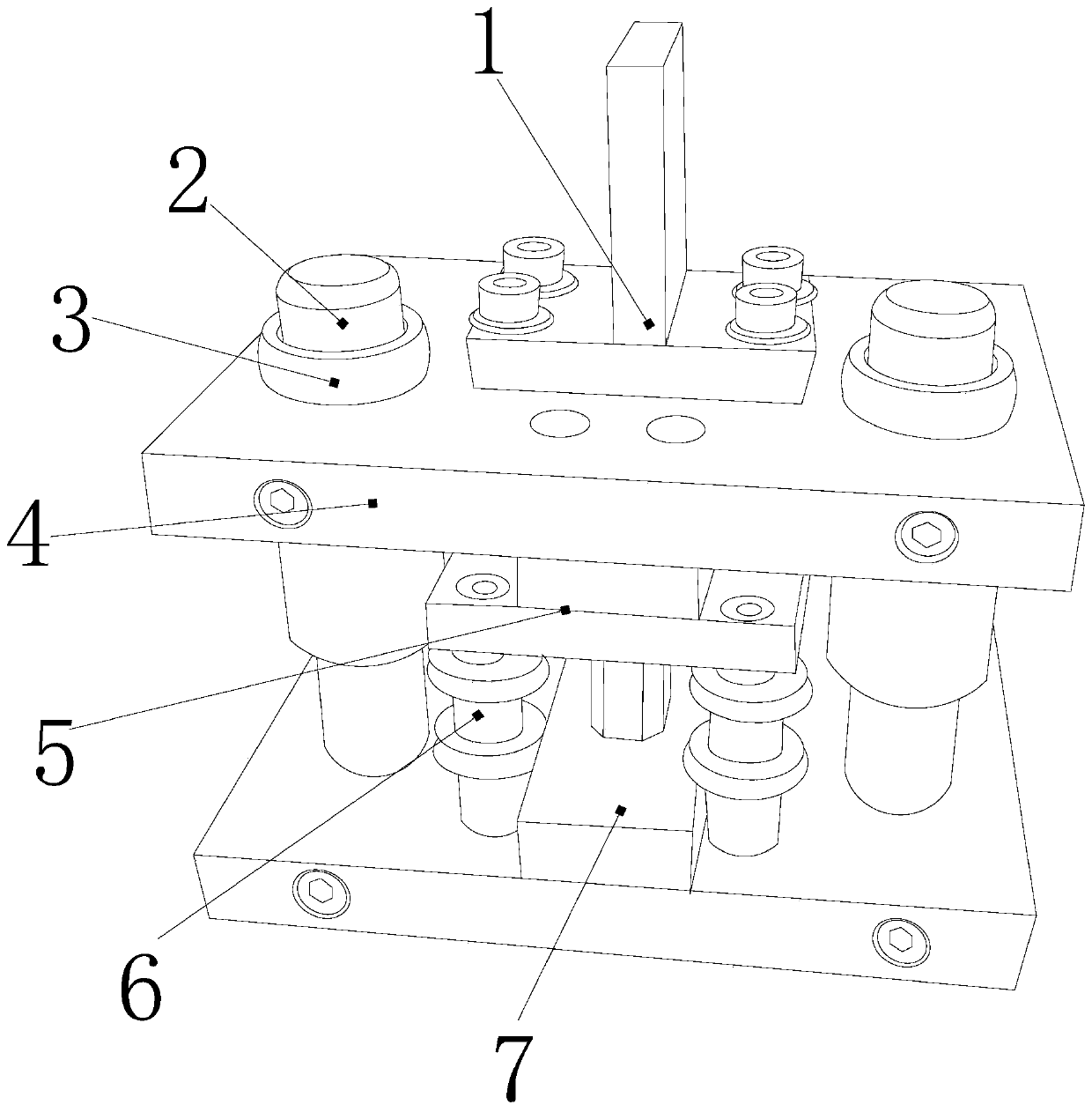
[0031] see Figure 1-Figure 7 , the present invention provides a kind of punching processing mold equipment based on the cutting and pressing of special-shaped seamless steel pipe arc section. Mold cover plate 5, alignment arch shaft column 6, base block 7, the alignment arch shaft column 6 is provided with four and respectively inserted under the four corners of the curved mold cover plate 5, the The bending die cover plate 5 is mechanically connected with the base block 7 through the alignment bracket shaft column 6. The upper parting panel 4 and the bending die cover plate 5 are in close contact with each other and are on the same horizontal plane. The T-shaped pressing pin The block 1 is welded on the top surface of the upper parting panel 4,...


PUM


Abstract

The invention discloses a punching machining die device based on special-shaped seamless steel pipe arc section blanking and pressing. The punching machining die device is characterized by structurally comprising a T-shaped pressure pin block, sliding pin column jackets, sleeves, an upper parting panel, a bending die cover plate, counterpoint bow frame shaft pillars and a base block. By means of the punching machining die device, the bending die cover plate is matched with the counterpoint bow frame shaft pillars, an aluminum slag plate is removed in a rolling friction manner, and padding of an insulation pad is avoided; then light ray correlation shaft frames are used for conducting auxiliary operation on a punching pile, a deep-correction left-right cooperation clamping rolling output effect is formed, and a slag discharging and discharging punching auxiliary matching effect is achieved; then rotation lasers are corrected to be emitted to a middle position point in a correlation manner so that the punching pile can have a lower position end crosshair, and the punching precision and the depth limitation are improved; the blanking progress of a special-shaped pipe can be rapid andefficient, a single-pipe multi-punch-hole homeopathic sliding and pushing slag discharging effect is also enhanced, when a bending die is subjected to die pressing, impact locking can be conducted onan arc top face of the pipe, hydraulic force of insertion pin pillars at the two ends rises again, the stress mark and garland probability of a steel pipe face is lowered, and punching completeness isensured.

Description

technical field [0001] The invention relates to punching processing die equipment based on the arc section cutting and pressing of special-shaped seamless steel pipes, which belongs to the field of dies. Background technique [0002] The punching efficiency of the stamping die is high. It is a precise equipment for batch processing of pipe fittings and plate parts. It is an integrated processing efficiency from the molding and locking of the mold to the final punching and forming of the mold, which shortens the processing process and can Manually try to adjust the deviation, fit and fit the parting surface operation, and the surface-matching shape of the special-shaped pipe and the punching die will ensure that the deformation of the pipe will not be too large. The shortcomings of the current technology that need to be optimized are: : [0003] The aluminum curved surface of the aluminum alloy special-shaped steel pipe has a large tension, so that when the punching operatio...

Claims


Application Information

Patent Timeline
IPC IPC(8): B21D28/28B21D28/34B21C51/00B24B27/033
CPCB21C51/00B21D28/28B21D28/34B24B27/033
Inventor 张少龙
Owner 西安美汉电气工程有限公司
Why Eureka
Try Eureka