Special trimming machine for high-precision laser positioning die ejector rod

A laser positioning and mold ejector technology, which is applied in the direction of manufacturing tools, grinding/polishing equipment, grinding machine parts, etc., can solve the problem of large errors in the flatness and dimensional accuracy of ejector pins, which cannot be used in mold production and processing Requirements, poor effect of ejector rod grinding, etc., to achieve the effect of ensuring grinding accuracy, ensuring grinding quality, and convenient maintenance and disassembly

Pending Publication Date: 2019-10-22
十堰天凯模具制造有限公司
View PDF1 Cites 0 Cited by
  • Summary
  • Abstract
  • Description
  • Claims
  • Application Information

AI Technical Summary

Problems solved by technology

[0004] When the existing similar mold repairing machines are in use, the grinding effect on the ejector rod is poor, and it mostly relies on the workers to operate the ejector rod. It is cumbersome; and the flatness and dimensional accuracy of the ejector rod after grinding have large errors, which cannot meet the requirements for mold production and processing.

Method used


Image

  • Special trimming machine for high-precision laser positioning die ejector rod
  • Special trimming machine for high-precision laser positioning die ejector rod
  • Special trimming machine for high-precision laser positioning die ejector rod

Examples


Embodiment

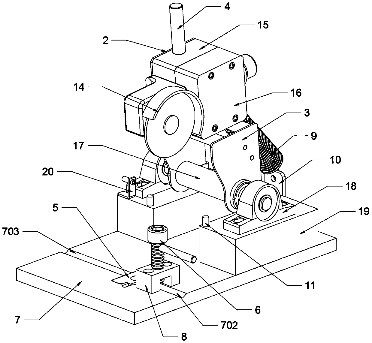
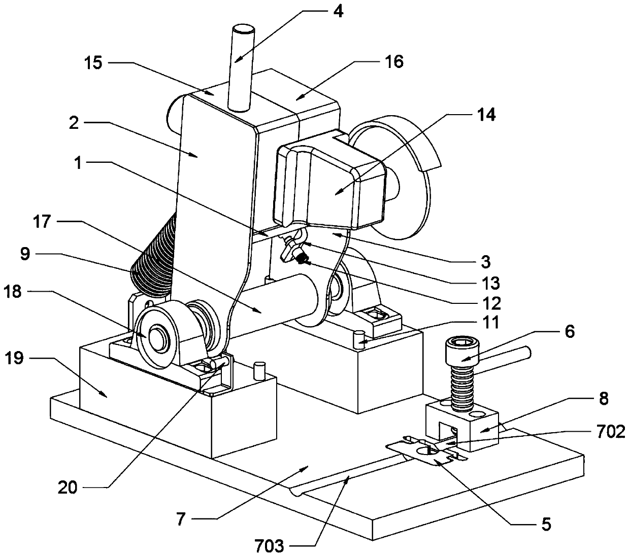
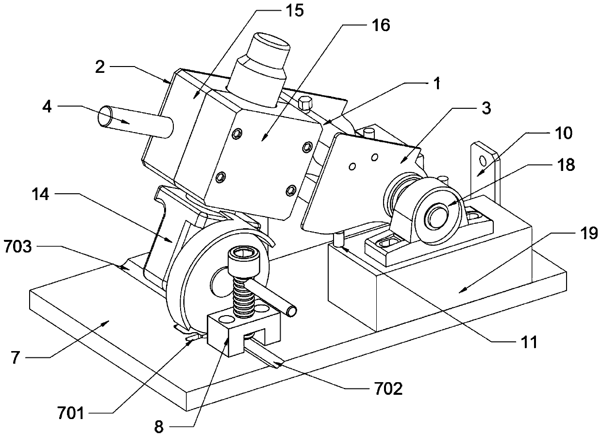
[0031] as attached figure 1 to attach Figure 6 Shown:

[0032]The present invention provides a high-precision laser positioning mold ejector pin dedicated mold repairing machine, which includes a main and auxiliary connecting rod 1, a cutting head main board 2, a cutting head auxiliary board 3, a pressing handle 4, a positioning cutting block 5, and a positioning round hole 501, Positioning screw 6, base 7, grinding groove 701, V-shaped positioning groove 702, ejector rod escape groove 703, ejector rod locking pressure block 8, spring 9, spring hanging plate 10, support column 11, laser marking line Device 12, laser assembly block 13, angle grinder 14, angle grinder installation block 15, angle grinder disassembly block 16, rotating shaft 17, bearing 18, bearing support seat 19 and proximity switch 20; the main and auxiliary connecting rod 1 There are two places, and the left end of the main and auxiliary connecting rod 1 is connected to the inner wall on the right side of ...


PUM


Abstract

The invention provides a special trimming machine for a high-precision laser positioning die ejector rod. The special trimming machine comprises an angle grinder, an angle grinder mounting block and an angle grinder dismounting block. Two main and auxiliary connecting rods are arranged, the left ends of the main and auxiliary connecting rods are connected to the inner wall of the right side of a cutting head main board, the right ends of the main and auxiliary connecting rods are connected to the inner wall of the left side of a cutting head auxiliary board, the bottoms of the cutting head main board and the cutting head auxiliary board are respectively sleeved and fixed on the outer end surfaces of the left side and the right side of a rotating shaft, the left end and the right end of therotating shaft are rotatably connected in two bearings correspondingly, and a pressing handle is mounted on the top end face of the angle grinder mounting block. Linear laser light is projected to agrinding groove part through a linear laser marker, the rotary trimming portion of the angle grinder is marked, so that personnel can adjust the position of the ejector rod inside a grinding groove according to the laser projection part of the linear laser marker, and the grinding precision of the ejector rod is guaranteed.

Description

technical field [0001] The invention belongs to the technical field of mold ejector pin processing, and more specifically relates to a special mold repairing machine for high-precision laser positioning mold ejector pins. Background technique [0002] In the mold production process, the grinding of the ejector pin is a necessary process for each set of molds. [0003] The model repairing machine can refer to the CN207901075U patent, which mainly includes a workbench, at least one mold repairing mechanism on the workbench, a storage box on the workbench, a cabinet under the workbench, and a cabinet located on the workbench. The hook on at least one side of the workbench; the mold repairing mechanism includes a roller frame, a roller mounted on the roller frame, a fastening screw connecting the roller frame and the roller, and its number is two, two The distance between the rollers is adjustable, the surface of the rollers is provided with a rough structure, and the rough str...

Claims


Application Information

Patent Timeline
Patent Type & Authority Applications(China)
IPC IPC(8): B24B19/20B24B19/00B24B41/06B24B41/00
CPCB24B19/20B24B19/00B24B41/06B24B41/00
Inventor 孙宇涛张浩金立春孔红
Owner 十堰天凯模具制造有限公司
Why Eureka
Try Eureka