
Crankshaft transfer trolley capable of automatically moving up and down

A technology for automatic lifting and transfer vehicles, applied to motor vehicles, multi-axis trolleys, trolleys, etc., can solve the problems of reducing efficiency and increasing labor intensity of the crankshaft, and achieve the effects of reducing labor intensity, smooth movement, and ensuring stability

Active Publication Date: 2019-10-22
CHONGQING CHANGAN AUTOMOBILE CO LTD
View PDF8 Cites 1 Cited by
  • Summary
  • Abstract
  • Description
  • Claims
  • Application Information

AI Technical Summary

Problems solved by technology

[0005] However, the above two patents cannot solve the problem of increasing labor intensity and reducing efficiency when picking up the crankshaft at a lower position

Method used


Image

  • Crankshaft transfer trolley capable of automatically moving up and down
  • Crankshaft transfer trolley capable of automatically moving up and down
  • Crankshaft transfer trolley capable of automatically moving up and down

Examples


Embodiment Construction

[0054] The technical solutions of the present invention will be further described below in conjunction with the accompanying drawings and embodiments.

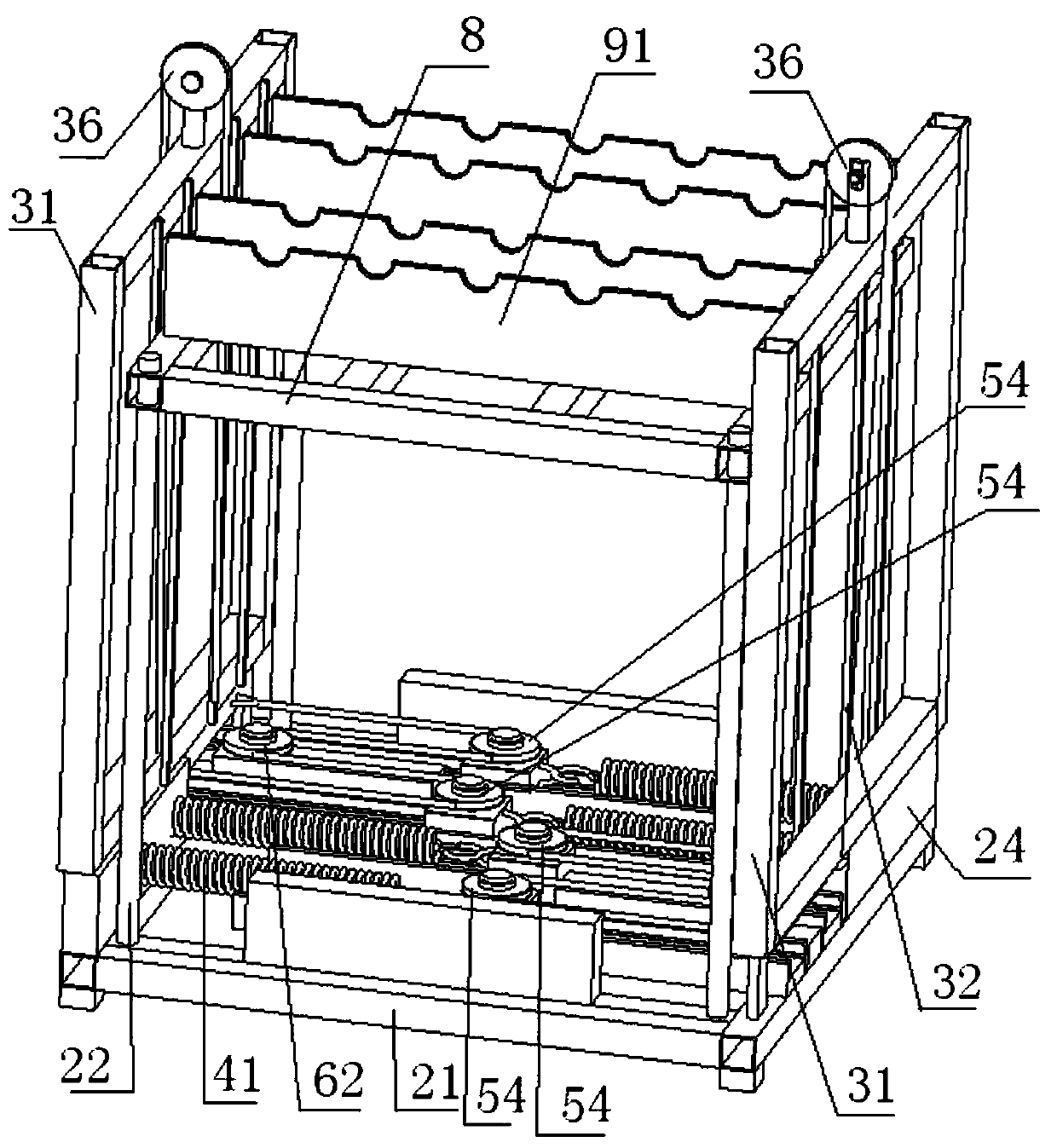
[0055] see figure 1 , an automatic lifting crankshaft transfer vehicle, comprising a frame 1, a driving device installed on the frame, a lifting frame 8 and a crankshaft support plate 9;

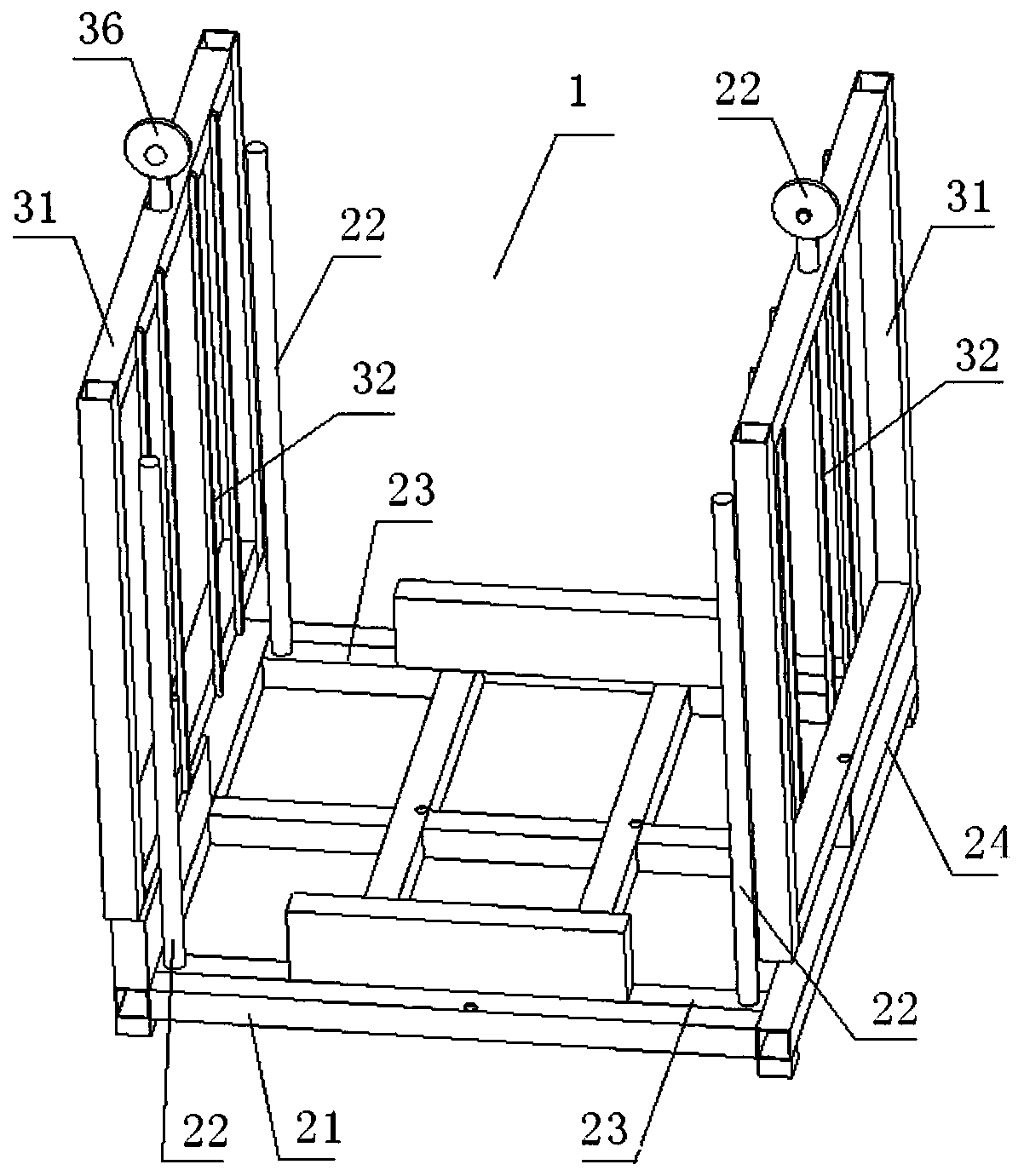
[0056] see figure 2 , the rack 1 includes a rack body 2 and a baffle 3;

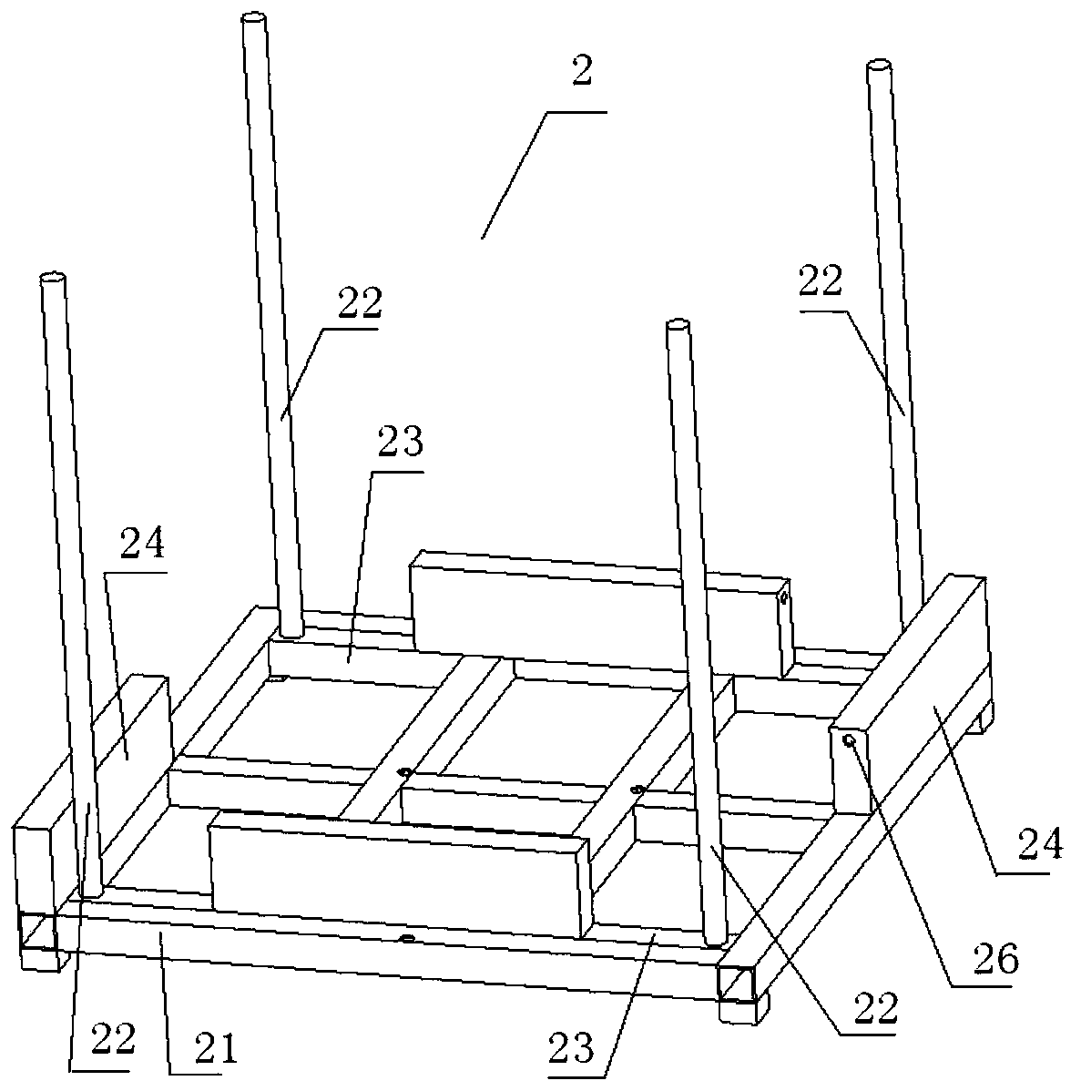
[0057] see image 3 , Figure 4 , the frame body 2 includes a base 21, a guide column 22 installed on the base 21, and the edge of the base 21 has a side support plate 24;

[0058] see Image 6 , the baffle 3 includes a baffle frame 31 and a guide bar 32 installed on the baffle frame 31, the first pulley assembly 34 is installed on the baffle frame 31, and the first pulley assembly 34 includes a first pulley 36;

[0059] see figure 1 , the lifting frame 8 is slidably matched with the guide column 22, the baffle frame 31 is fixed on the bottom plate 21, the cra...


PUM


Abstract

The invention relates to a crankshaft transfer trolley capable of automatically moving up and down. The crankshaft transfer trolley comprises a rack, a crane, a crankshaft support plate and a drivingdevice; the rack comprises a rack body and baffle plates; the rack body comprises a base and guide pillars; side support plates are arranged at the edges of the base; the baffle plates comprise baffleplate frames and guide strips; a first pulley is arranged on each baffle plate frame; the crane is in sliding fit with the guide pillars; the driving device comprises movable pulley modules, fixed pulley modules, limiting plate modules, springs and a steel rope which are fixed on the base; each movable pulley module comprises a movable pulley; each fixed pulley module comprises a fixed pulley; each limiting plate module comprises a limiting plate and a second pulley; one end of each spring is connected to one side support plate, and the other end is connected to each movable pulley; the steelrope bypasses the movable pulleys, the fixed pulleys, the second pulleys and the first pulleys; and one end of the steel rope is fixed on one limiting plate, and the other end is fixed on the crane.Through the crankshaft transfer trolley disclosed by the invention, the crankshaft always can float at a certain height, thereby preventing an operator from bending down and reducing the labor intensity.

Description

technical field [0001] The invention relates to crankshaft transportation, in particular to an automatic lifting crankshaft transfer vehicle. Background technique [0002] After the crankshaft is manufactured, it needs to be stored in the material area. During assembly, the crankshaft needs to be transferred from the material area to the assembly station of the engine assembly line. In order to reduce labor intensity, the crankshaft is usually transferred by a transfer vehicle. Take it out from the transfer vehicle. The crankshafts are placed in layers on the transfer vehicle, and it is necessary to bend down when picking up the lower crankshafts. This method not only increases labor intensity, poses occupational health hazards, but also reduces production efficiency and increases manufacturing costs. [0003] CN102582671A discloses a crankshaft revolving car, which is provided with a base plate and a wheel set, four uprights and a frame are welded on the base plate, and tw...

Claims


Application Information

Patent Timeline
IPC IPC(8): B62B3/10B62B3/04B62B5/00
CPCB62B3/04B62B3/104B62B5/00
Inventor 朱洪磊尧琼林李加彬朱锦张劲松黄涛
Owner CHONGQING CHANGAN AUTOMOBILE CO LTD
Learn More