Supercharge Your Innovation With Domain-Expert AI Agents!

Electromagnetic valve for adjusting damping of shock absorber

A solenoid valve and shock absorber technology, applied in the field of auto parts, can solve the problems of low damping force linearity, slow solenoid valve action, low control precision, etc., and achieve high control stability, fast response speed, and high control precision. Effect

Pending Publication Date: 2019-10-22
MIANYANG FULIN PRECISION MACHINING
View PDF0 Cites 3 Cited by
  • Summary
  • Abstract
  • Description
  • Claims
  • Application Information

AI Technical Summary

Problems solved by technology

Due to the single-channel throttling of traditional solenoid valves, it is difficult to achieve a wider adjustment range in a limited range of motion, resulting in little change in the compression force and rebuttal force of the shock absorber within a certain current range
[0005] (2) Slow response
The adjustment hysteresis is large, which leads to the slow action of the solenoid valve, which reduces the response speed of the shock absorber assembly
[0006] (3) Low control precision
Due to the small adjustment range of the solenoid valve for adjusting the damping of the shock absorber, a small current change in the adjustment range will cause a large opening change of the solenoid valve, resulting in a decrease in control accuracy
[0007] (4) The linearity of the damping force is low

Method used


Image

  • Electromagnetic valve for adjusting damping of shock absorber
  • Electromagnetic valve for adjusting damping of shock absorber
  • Electromagnetic valve for adjusting damping of shock absorber

Examples


Embodiment

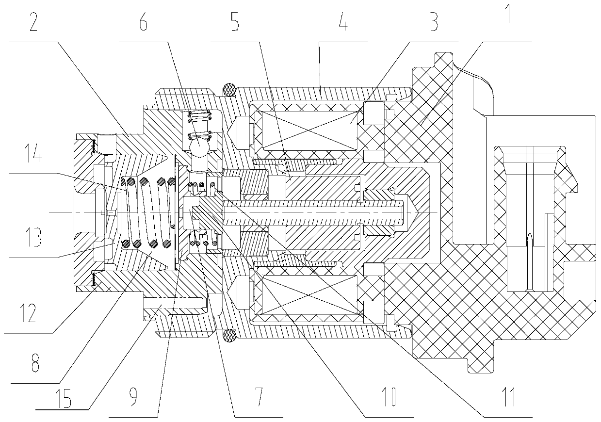
[0039] This embodiment provides a solenoid valve for adjusting the damping of the shock absorber, please refer to figure 1 , the electromagnetic valve for adjusting the damping of the shock absorber includes an electromagnetic drive subassembly 1 and a valve body subassembly 2;

[0040] The electromagnetic drive sub-assembly 1 and the valve body sub-assembly 2 are connected through interference, and the electromagnetic drive sub-assembly 1 provides power for the valve body sub-assembly 2 .

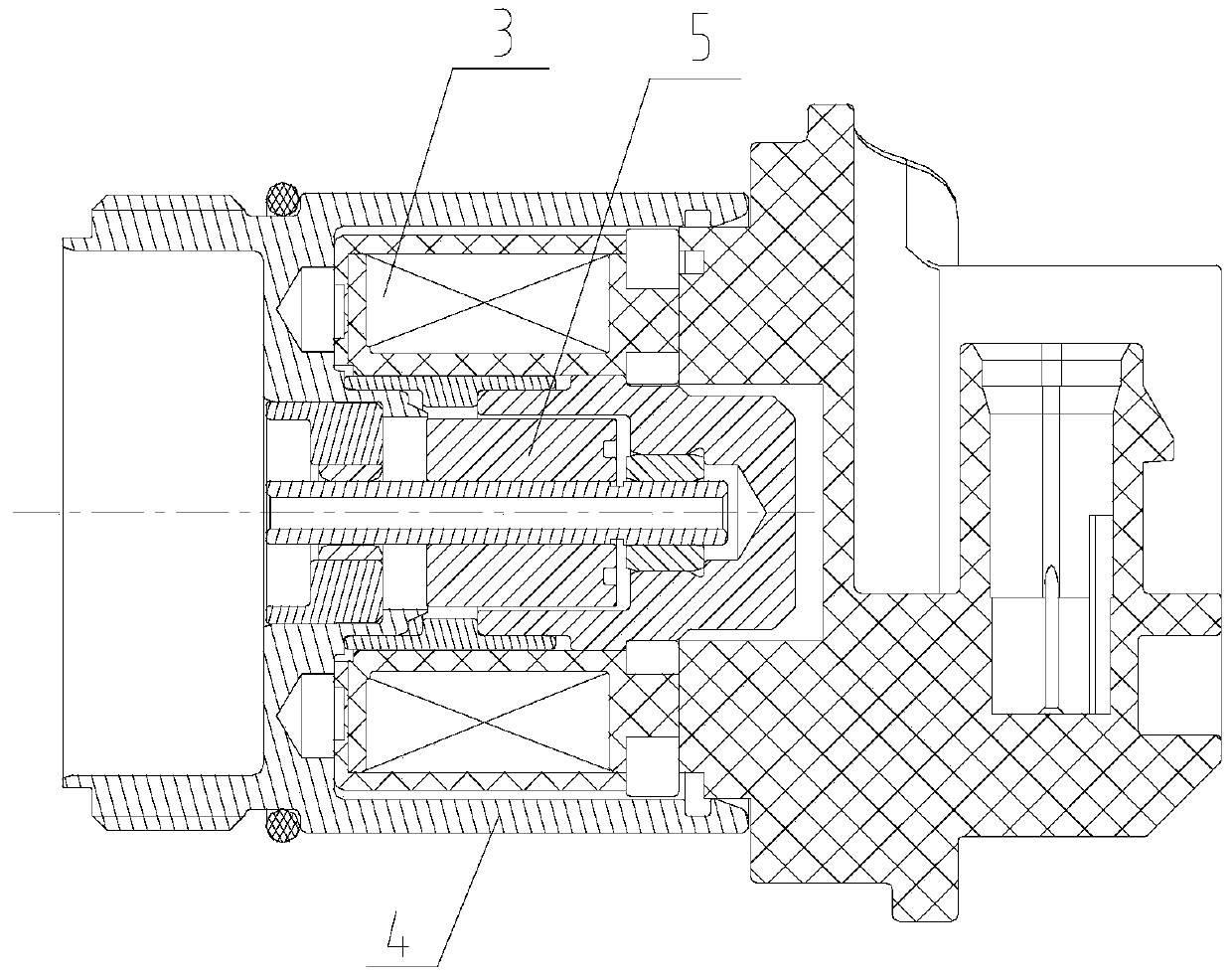
[0041] see figure 2 , the electromagnetic drive subassembly 1 includes an electromagnetic coil 3, a housing subassembly 4 and a magnetic core subassembly 5, the electromagnetic coil 3 is fixed in a cavity formed by the housing subassembly 4, and the magnetic core subassembly 5 is connected to the housing The bearings provided in the sub-assembly 4 are clearance fit so that the magnetic core sub-assembly 5 can slide axially in the cavity of the housing sub-assembly 4 . The electromagneti...


PUM


Abstract

The invention provides an electromagnetic valve for adjusting damping of a shock absorber, and belongs to the field of automobile parts. The electromagnetic valve for adjusting damping of the shock absorber comprises an electromagnetic drive sub-assembly and a valve body sub-assembly, wherein the electromagnetic drive sub-assembly comprises an electromagnetic coil and a magnetic core sub-assemblyarranged in a shell sub-assembly; the valve body sub-assembly comprises an outer valve sleeve fixedly connected with the shell sub-assembly and a pilot valve arranged inside the outer valve sleeve; the pilot valve comprises an inner valve sleeve and a control valve core; one end, far away from the inner valve sleeve, of the control valve core can be in abutting fit with the magnetic core sub-assembly; the inner valve sleeve is provided with an axial oil inlet opening and closing hole matched with the shaft end of the control valve core and a circumferential oil outlet opening and closing holematched with the peripheral side of the control valve core; the side surface of one end, far away from the inner valve sleeve, of the control valve core is provided with a bottom hole communicating with a circumferential oil outlet opening and closing hole and a pilot oil outlet through-flow section hole; and the pilot oil outlet through-flow section hole is used for oil to flow out of the pilot valve. The electromagnetic valve for adjusting damping of the shock absorber has the advantages of faster response speed, higher control stability, higher control precision, higher linearity and the like.

Description

technical field [0001] The invention relates to the field of auto parts, in particular to a solenoid valve for adjusting the damping of a shock absorber. Background technique [0002] Traditional shock absorbers have fixed characteristics, providing a fixed damping characteristic curve in the process of extension or compression, while adjustable shock absorbers provide a characteristic field, the system according to the working conditions (road conditions, braking, acceleration, turning, driving In order to curb the vibration of the vehicle body, prevent the tires from beating, and keep the vehicle body stable. Variable damping shock absorbers are mainly realized by magneto-rheological, solenoid valve type, stepping motor type, etc. The solenoid valve type is widely used due to its reliable performance, low cost, quick response, and compact structure. [0003] Although the electromagnetic valve type variable damping shock absorber is more and more widely used at home and ab...

Claims


Application Information

Patent Timeline
Patent Type & Authority Applications(China)
IPC IPC(8): F16F9/34F16F9/50
CPCF16F9/34F16F9/50F16F2222/06F16F2228/066
Inventor 陈磊李贞丽张金伟郑翰林蒲文东张爱欢孟勇
Owner MIANYANG FULIN PRECISION MACHINING
Features
  • R&D
  • Intellectual Property
  • Life Sciences
  • Materials
  • Tech Scout
  • Unparalleled Data Quality
  • Higher Quality Content
  • 60% Fewer Hallucinations
Learn More