Supercharge Your Innovation With Domain-Expert AI Agents!

LiDAR-Camera Joint Calibration Target and Joint Calibration Method

A laser radar and joint calibration technology, applied in the direction of radio wave measurement systems, instruments, etc., can solve the problems of not getting distance values ​​at the edge and low angular resolution, and achieve simple structure, low production cost, and save calibration costs Effect

Active Publication Date: 2021-03-12
SUZHOU UNION INTELLIGENT TECH CO LTD
View PDF20 Cites 0 Cited by
  • Summary
  • Abstract
  • Description
  • Claims
  • Application Information

AI Technical Summary

Problems solved by technology

However, due to the particularity of scanning lidar, its angular resolution is low, usually only 0.15°-3°, and due to the influence of mixed pixels, the edge part of the distance mutation often cannot get accurate distance value

Method used


Image

  • LiDAR-Camera Joint Calibration Target and Joint Calibration Method
  • LiDAR-Camera Joint Calibration Target and Joint Calibration Method
  • LiDAR-Camera Joint Calibration Target and Joint Calibration Method

Examples


Embodiment 1

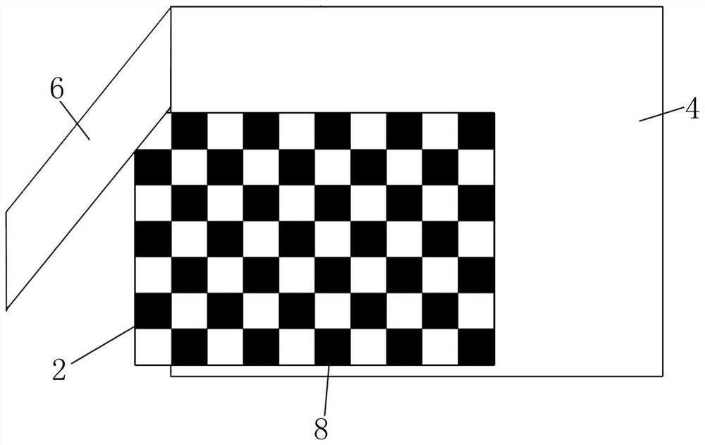
[0036] This embodiment discloses a lidar-camera joint calibration target, refer to figure 1 As shown, the joint calibration target includes a checkerboard calibration board 2 and an "L"-shaped calibration board; the above-mentioned "L"-shaped calibration board includes a first plane vertical board 4 and a second plane vertical board 6, and the above-mentioned second plane vertical board 6 is opposite Fix on the first plane riser 4 after the first plane riser 4 turns 90°; the above-mentioned checkerboard marking plate 2 is parallel to the first plane riser 4, and is fixed on the front side of the line of sight of the first plane riser 4 A black and white checkerboard pattern 8 is arranged on the above-mentioned checkerboard calibration board 2 on a plane vertical board 4 .

[0037] The joint calibration target of the above structure, the checkerboard calibration plate 2 is a flat plate structure, and the black and white checkerboard pattern 8 is regularly arranged on it; in the...

Embodiment 2

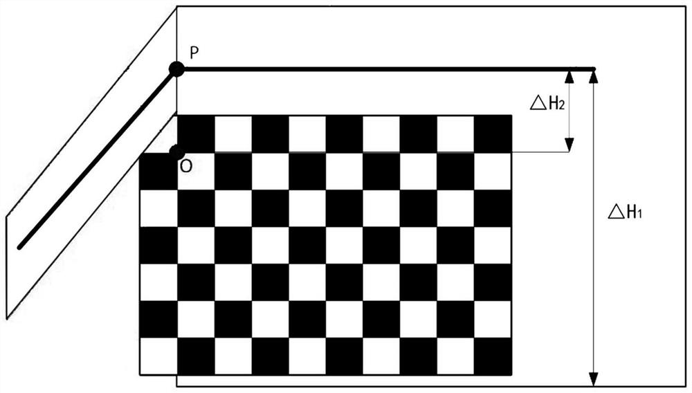
[0041] This embodiment discloses a lidar-camera joint calibration method. The joint calibration target disclosed in Embodiment 1 is used for joint calibration of the lidar-camera. The calibration target is placed within the field of view of the two cameras of the two cameras, and placed At a distance of about 2 meters from the lidar (the ranging range of the lidar is 4 meters). Here, the internal parameters of the camera have been calibrated using methods in the prior art.

[0042] The joint calibration method includes the following specific steps:

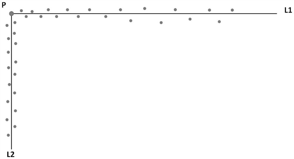
[0043] (1) The laser radar scans the "L"-shaped calibration plate to obtain the relative positional relationship between the laser radar and the "L"-shaped calibration plate [R 1 , T 1 ].

[0044] The specific implementation process of this step is as follows:

[0045] S1, the laser radar continuously scans the first plane riser 4 and the second plane riser 6, and can scan continuously from the first plane riser 4 to the secon...


PUM


Abstract

A laser radar-camera joint calibration target and a joint calibration method, wherein the joint calibration target comprises a checkerboard calibration plate (2) and an "L" shaped calibration plate; the "L" shaped calibration plate includes a first planar vertical plate (4) and a second planar vertical plate (6), the second planar vertical plate (6) is fixed on the first planar vertical plate (4) after turning 90° relative to the first planar vertical plate (4); the checkerboard calibration plate (2) is parallel to the first planar vertical plate (4), located at the front side of the line of sight of the first planar vertical plate (4) and fixed on the first planar vertical plate (4), a black and white checkerboard pattern (8) is arranged on the checkerboard calibration plate (2), the laser radar-camera joint calibration target completes the joint calibration of the laser radar and the camera under the condition that both a sensor and the calibration target do not move, can overcome the practical use limitation of the laser radar with low angular resolution, obtain an accurate distance value of the edge portion of the distance mutation, has the characteristics of simple structure and low manufacturing cost, and is suitable for batch calibration.

Description

technical field [0001] The invention belongs to the technical field of multi-sensor joint calibration, and in particular relates to a laser radar-camera joint calibration target, and also relates to a method for using the joint calibration target to perform joint calibration of the laser radar-camera. Background technique [0002] In the visual navigation of intelligent robots, using multi-sensor data fusion technology, a more reliable, unified, and detailed description of the environment can be obtained for decision-making, planning, and control. When performing pixel-level data fusion, multi-sensor calibration is one of the problems that must be solved. Calibration is generally divided into two parts: the calibration of each sensor's own parameters and the joint calibration of multiple sensors. The calibration of each sensor's own parameters is to ensure the accuracy of the collected data, and the joint calibration of multiple sensors is to accurately match the multi-sens...

Claims


Application Information

Patent Timeline
Patent Type & Authority Patents(China)
IPC IPC(8): G01S7/497
CPCG01S7/497
Inventor 王国举刘慧林
Owner SUZHOU UNION INTELLIGENT TECH CO LTD
Features
  • R&D
  • Intellectual Property
  • Life Sciences
  • Materials
  • Tech Scout
  • Unparalleled Data Quality
  • Higher Quality Content
  • 60% Fewer Hallucinations
Learn More