
Gearbox wire and modeling method thereof

A gearbox and wire technology, which is applied in the direction of conductive connection, line/collector parts, multi-core cable end parts, etc., can solve the problems of unusable and no finished wires, etc., and achieve space saving, firm shape and simple structure Effect

Pending Publication Date: 2019-10-22
上海李尔汽车部件有限公司
View PDF0 Cites 0 Cited by
  • Summary
  • Abstract
  • Description
  • Claims
  • Application Information

AI Technical Summary

Problems solved by technology

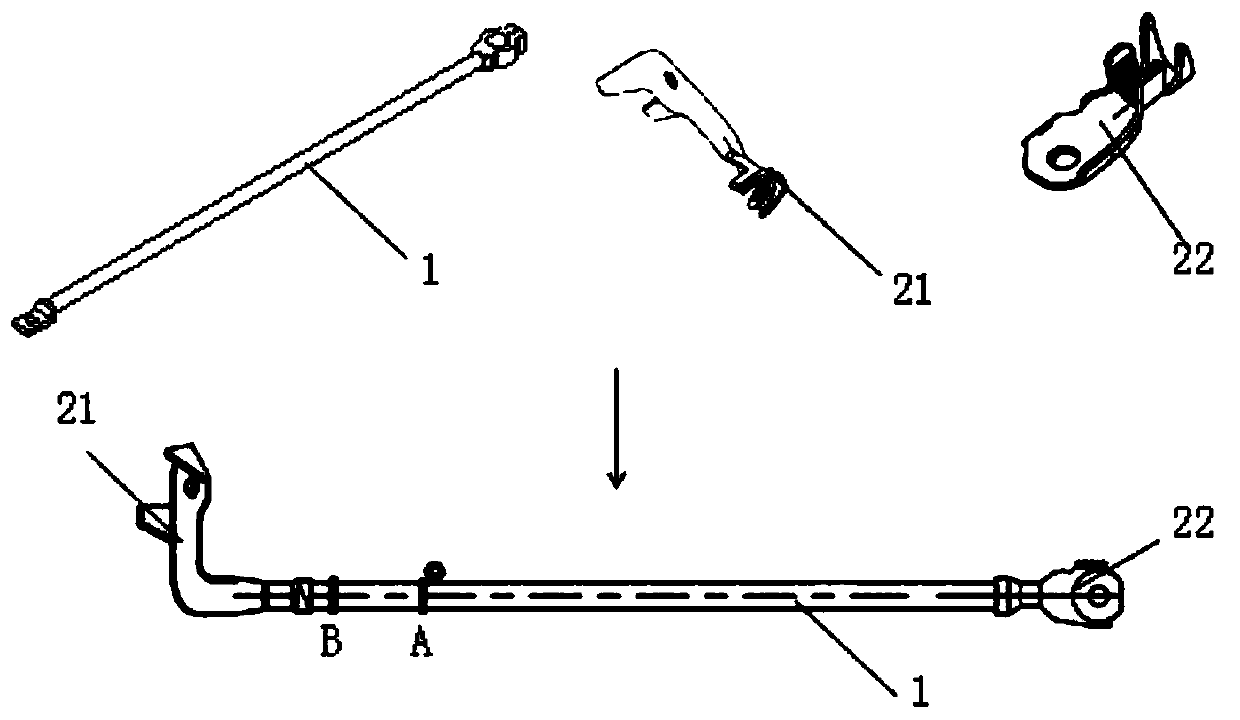
Due to the narrow space inside the gearbox, the corresponding wires need to avoid other mechanisms in the gearbox, so a simple straight line cannot be used, and a specific bending shape is required for the wires to meet the avoidance requirements, but there is no such thing in the market currently. Finished conductors for this requirement

Method used


Image

  • Gearbox wire and modeling method thereof
  • Gearbox wire and modeling method thereof
  • Gearbox wire and modeling method thereof

Examples


Embodiment Construction

[0037] The specific implementation manners of the present invention will be described in further detail below in conjunction with the accompanying drawings. These embodiments are only used to illustrate the present invention, not to limit the present invention.

[0038] In the description of the present invention, it should be noted that the orientation or positional relationship indicated by the terms "midpoint", "inner", "outer", etc. is based on the orientation or positional relationship shown in the drawings, and is only for the convenience of describing the present invention and simplified descriptions, rather than indicating or implying that the device or element referred to must have a specific orientation, be constructed and operate in a specific orientation, and thus should not be construed as limiting the invention. In addition, the terms "first" and "second" are used for descriptive purposes only, and should not be understood as indicating or implying relative impor...


PUM


Abstract

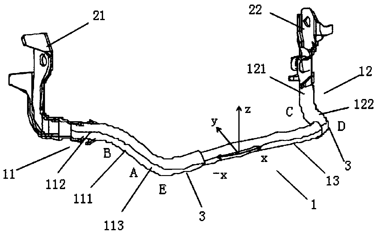
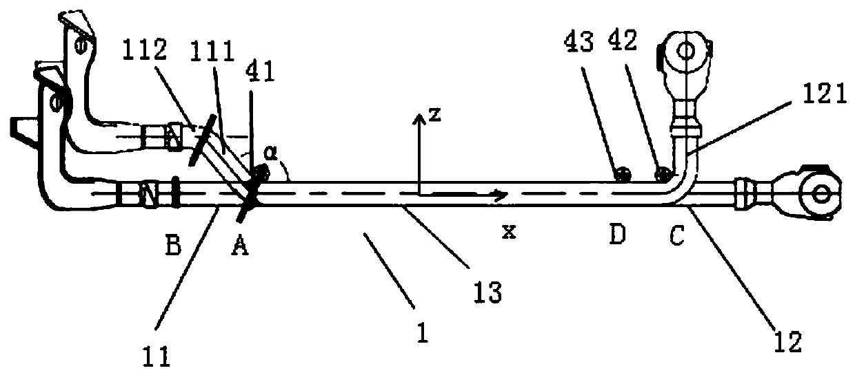
The invention provides a gearbox wire which comprises a left side bending section, a straight line section and a right side bending section which are connected in sequence; the outer side of the leftside bending section and the outer side of the right side bending section are sleeved in heat shrink tubes; the straight line section extends along positive and negative x-axis directions; the left side bending section comprises a third bending section, a first bending section and a second bending section which are all located in a second octant and connected in sequence; one end of the third bending section is connected with the left end of the straight line section; one end of the second bending section is connected with a left terminal in a pressing mode; and the right side bending sectioncomprises a fourth bending section positioned in the first octant and a fifth bending section parallel to the xy planes. The beneficial effects are that the structure is simple; modeling is firm; bending modeling of 25-square-millimeter wires is completed through plasticity improvement of the wire when the heat shrink tubes are heated at the high temperature; mutual avoidance of various mechanismsin the gearbox is achieved; and space is saved to the maximum extent.

Description

technical field [0001] The invention relates to a wire used inside a gearbox and a molding method for the wire. Background technique [0002] Most of the existing grounding wires use soft copper core wires of 25 square millimeters. Once the wires are cut, they can be directly crimped with the corresponding terminals to meet the use requirements. Due to the narrow space inside the gearbox, the corresponding wires need to avoid other mechanisms in the gearbox, so a simple straight line cannot be used, and a specific bending shape is required for the wires to meet the avoidance requirements, but there is no such thing in the market currently. Finished conductors for this requirement. Contents of the invention [0003] In view of the above defects, the technical problem to be solved by the present invention is to provide a gearbox wire that can meet the need for avoidance. [0004] The present invention provides a gearbox wire, both ends of the wire are crimped with terminal...

Claims


Application Information

Patent Timeline
IPC IPC(8): H01R11/01H01R11/11H01R43/00B21F1/00
CPCH01R11/01H01R11/11H01R43/00B21F1/00
Inventor 焦卫利杨振蕊许振威陈欢
Owner 上海李尔汽车部件有限公司
Learn More