
Laser pulse control system and laser pulse control method

A control system and laser pulse technology, applied in lasers, laser parts, phonon exciters, etc., can solve problems such as high cost, inconvenient control by users, and inflexible burst pulse forms.

Active Publication Date: 2019-10-22
深圳市大族微加工软件技术有限公司
View PDF9 Cites 3 Cited by
  • Summary
  • Abstract
  • Description
  • Claims
  • Application Information

AI Technical Summary

Problems solved by technology

[0004] However, the above-mentioned exemplary way to obtain burst pulses is not flexible enough, and it is not convenient for users to control, and for example, the burst-mode ultrafast laser of the main oscillation power amplification system has a complex structure and high cost

Method used


Image

  • Laser pulse control system and laser pulse control method
  • Laser pulse control system and laser pulse control method
  • Laser pulse control system and laser pulse control method

Examples


Embodiment Construction

[0056]In order to facilitate the understanding of the present invention, the present invention will be described more fully below with reference to the associated drawings. Preferred embodiments of the invention are shown in the accompanying drawings. However, the present invention can be embodied in many different forms and is not limited to the embodiments described herein. On the contrary, these embodiments are provided to make the understanding of the disclosure of the present invention more thorough and comprehensive.

[0057] Unless otherwise defined, all technical and scientific terms used herein have the same meaning as commonly understood by one of ordinary skill in the technical field of the invention. The terms used herein in the description of the present invention are for the purpose of describing specific embodiments only, and are not intended to limit the present invention.

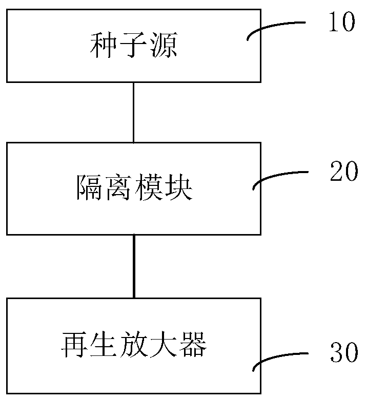
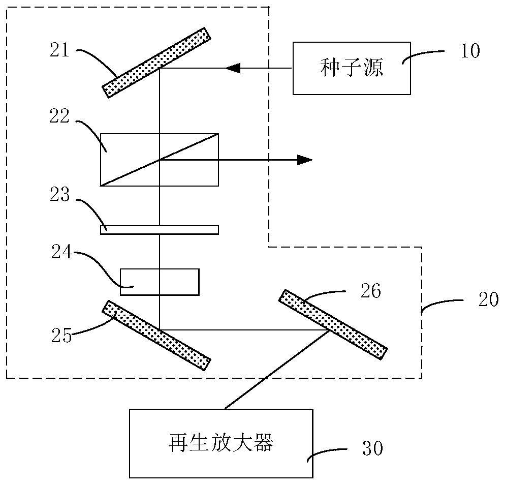
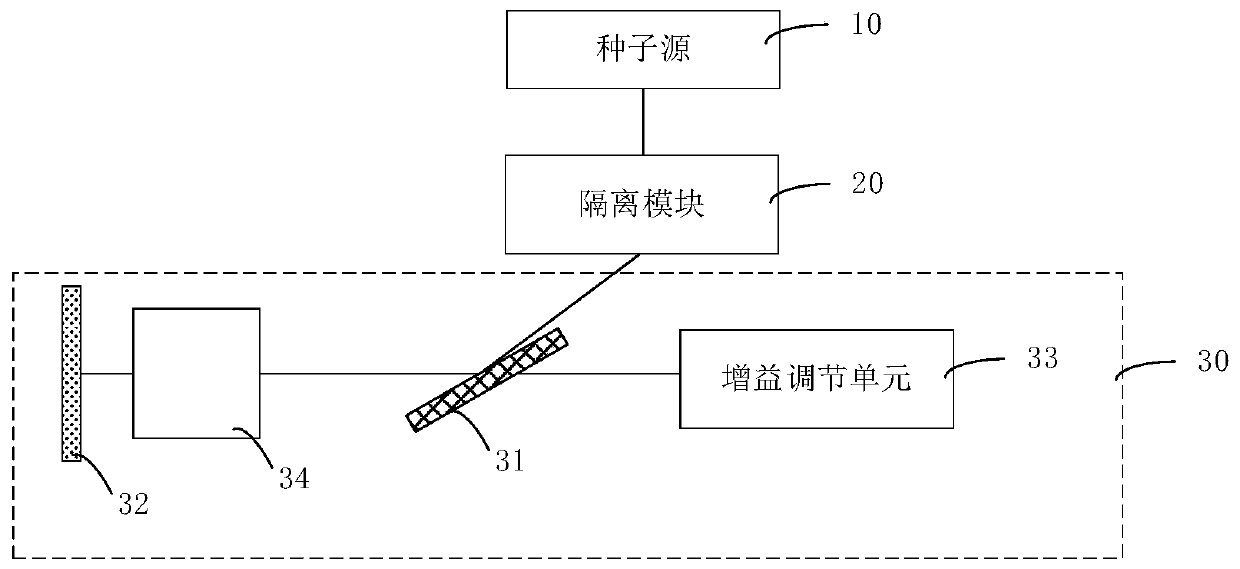
[0058] see figure 1 , figure 1 It is a system structure diagram of the laser pulse ...


PUM


Abstract

The invention relates to a laser pulse control system and a laser pulse control method. The laser pulse control system provides a first polarization pulse through a seed source. An isolation module converts the first polarization pulse into a second polarization pulse which can enter a regenerative amplifier through isolation processing, so that the regenerative amplifier performs polarization conversion and amplification in different modes on the pulse, single pulses or pulse strings with different pulse numbers and energy are obtained and output to the outside through the isolation module, so that flexible switching between different modes is achieved through a simple structure according to actual needs, use is convenient for users, and the laser processing requirement is better met.

Description

technical field [0001] The invention relates to the field of laser control, in particular to a laser pulse control system and a laser pulse control method. Background technique [0002] Ultrafast laser is the key technology in many fields such as laser processing. The damage caused by heat accumulation to the surrounding materials of the target position during laser processing, as well as the more significant nonlinear effect of materials caused by high laser intensity, make the processing quality and efficiency significantly and decrease. [0003] In order to improve the above situation, there are many exemplary ways, for example, by selecting a burst-mode ultrafast laser to process transparent materials, reducing the laser filamentation threshold, and lengthening the focal depth range of the beam, thereby reducing the accumulation of excess heat around the target processing position and improving Processing efficiency; for example, a burst pulse is obtained based on exter...

Claims


Application Information

Patent Timeline
IPC IPC(8): H01S3/10H01S3/11
CPCH01S3/10061H01S3/11
Inventor 张小军任莉娜邱越渭卢建刚尹建刚高云峰
Owner 深圳市大族微加工软件技术有限公司
Learn More