
Correction machine at front end of container

A container and calibrating machine technology, applied in the field of container maintenance, can solve the problems of low efficiency, high noise, high labor intensity, etc.

Pending Publication Date: 2019-10-25
中集世联达集装箱物流(深圳)有限公司
View PDF0 Cites 3 Cited by
  • Summary
  • Abstract
  • Description
  • Claims
  • Application Information

AI Technical Summary

Problems solved by technology

[0003] At present, in the process of container maintenance, the correction of the convex deformation of the front end surface is basically done manually by hammering the board surface with a hammer, which has obvious defects such as high labor intensity, low efficiency, and high noise.

Method used


Image

  • Correction machine at front end of container
  • Correction machine at front end of container
  • Correction machine at front end of container

Examples


Embodiment Construction

[0036] Typical implementations embodying the features and advantages of the present application will be described in detail in the following description. It should be understood that the present application can have various changes in different embodiments without departing from the scope of the present application, and that the descriptions and illustrations therein are illustrative in nature and not limiting this application.

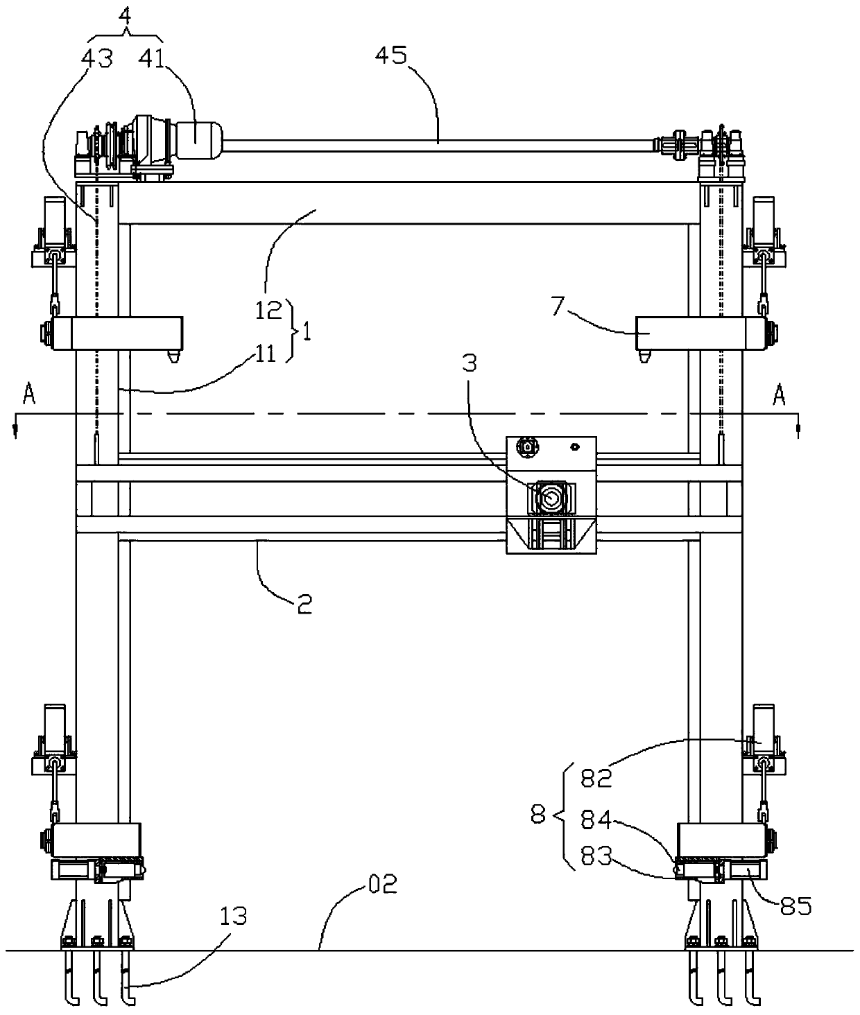
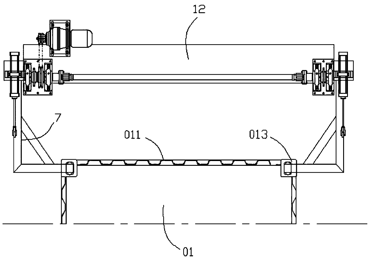
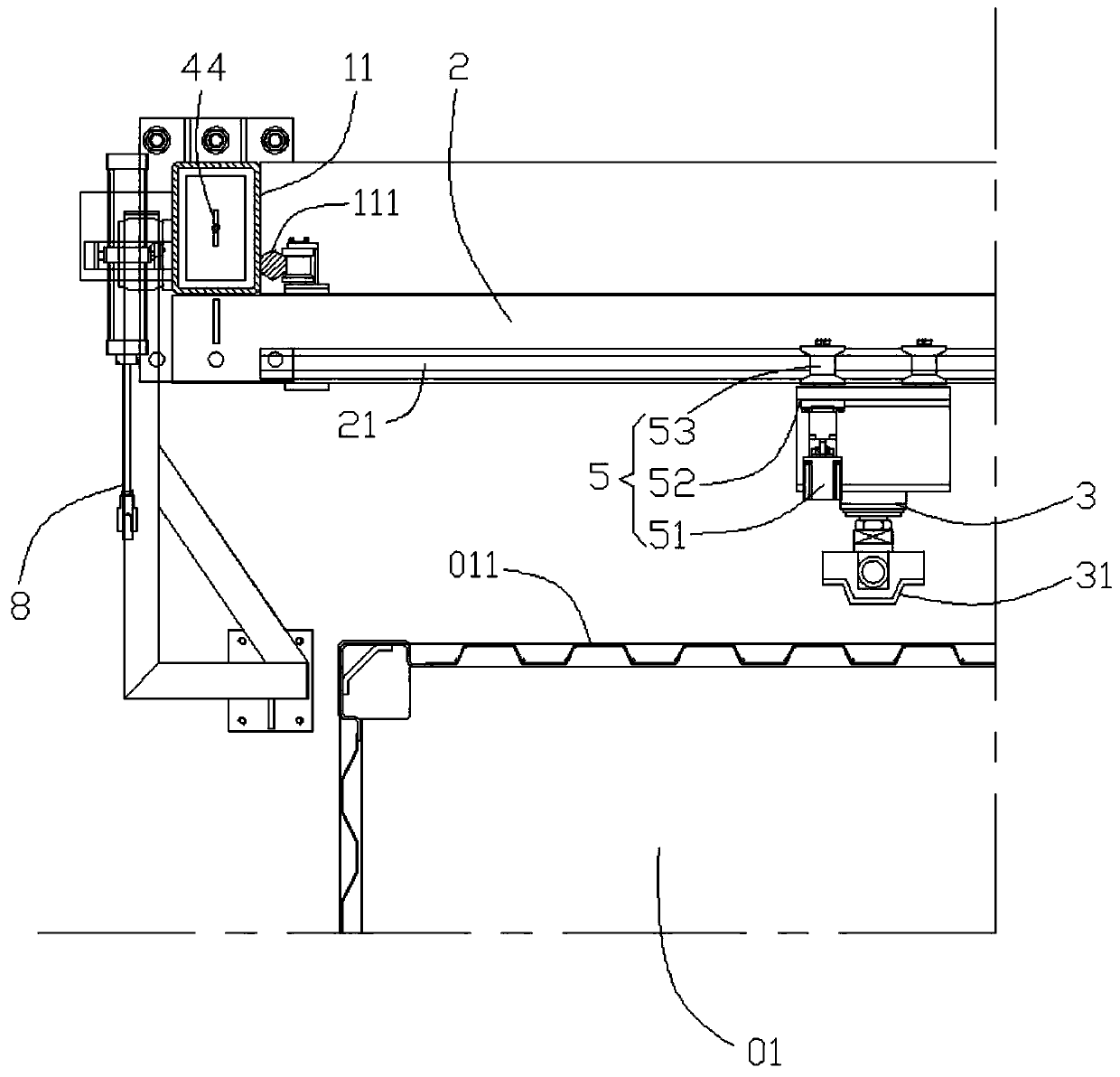
[0037] refer to Figure 1 to Figure 4 The embodiment of the present application provides a container front end correction machine, including a frame 1, a lifting beam 2, a hydraulic cylinder 3, a lifting drive mechanism 4, a lateral movement drive mechanism 5, a hook claw 6, an upper positioning mechanism 7 and a lower positioning mechanism 8.

[0038] The frame 1 includes two vertical beams 11 arranged at intervals and a fixed beam 12 fixedly connecting the two vertical beams 11 from the top, and the two vertical beams 11 are fixed to the ground 02...


PUM


Abstract

The invention provides a correction machine at the front end of a container. The correction machine comprises a rack, a lifting cross beam and a hydraulic cylinder. The lifting cross beam is arrangedon the rack in a manner of being capable of ascending and descending. A transverse guide rail is fixed to the lifting cross beam. The hydraulic cylinder is arranged on the lifting cross beam in a manner of being capable of transversely moving along the transverse guide rail. Thus, the hydraulic cylinder can be moved to any point in a plane range formed by the transverse range that the hydraulic cylinder moves along the transverse guide rail and the vertical range that the lifting cross beam ascends and descends. Then, the container is stopped at the correction position of the correction machine at the front end of the container, the front end face of the container and the movement plane of the hydraulic cylinder are parallel and meet a certain distance relation, the hydraulic cylinder canbe moved to the position right facing any outward protruding deformation portion on the front end face of the container, a piston rod is pushed out by the hydraulic cylinder so that the outward protruding deformation portion can be extruded and corrected through the ejection pressure of the piston rod, labor intensity and work noise are greatly reduced, and work efficiency is improved.

Description

technical field [0001] The present application relates to the technical field of container maintenance, in particular to a container front end correction machine. Background technique [0002] The ISO standard container will inevitably be bumped by the goods in the box during loading or transportation. Due to the thin wall thickness of the container, it is easy to have convex deformation on the front face (also called the front wall) of the container. [0003] At present, in the process of container maintenance, the correction of the convex deformation of the front end surface is basically done manually by hammering the board surface with a hammer, which has obvious defects such as high labor intensity, low efficiency, and high noise. [0004] Therefore, a device for correcting the convex deformation of the front end of the container is needed to solve the problems in the prior art. Contents of the invention [0005] In order to solve the above technical problems, the pre...

Claims


Application Information

Patent Timeline
Patent Type & Authority Applications(China)
IPC IPC(8): B21D1/08
CPCB21D1/08
Inventor 周红军夏海军华松钟维新何红亮梅鑫泽冷应田
Owner 中集世联达集装箱物流(深圳)有限公司
Learn More