Stamping device for automotive body accessory processing

A technology for automobile body and stamping device, applied in the field of stamping device, can solve the problems of stamping part error, plate inclination, etc., and achieve the effect of avoiding skew and facilitating adjustment

Inactive Publication Date: 2019-10-25
十堰市寅云实业有限公司
View PDF0 Cites 3 Cited by
  • Summary
  • Abstract
  • Description
  • Claims
  • Application Information

AI Technical Summary

Problems solved by technology

[0003] At present, most of the existing stamping devices for the processing of automobile body parts on the market have the following deficiencies: when stamping, the staff manually pushes the plate forward, which may make the plate tilt, which in turn leads to errors in the stamping parts. To sum up, Most of the existing stamping devices can not meet the actual needs well

Method used


Image

  • Stamping device for automotive body accessory processing
  • Stamping device for automotive body accessory processing
  • Stamping device for automotive body accessory processing

Examples


Embodiment 1

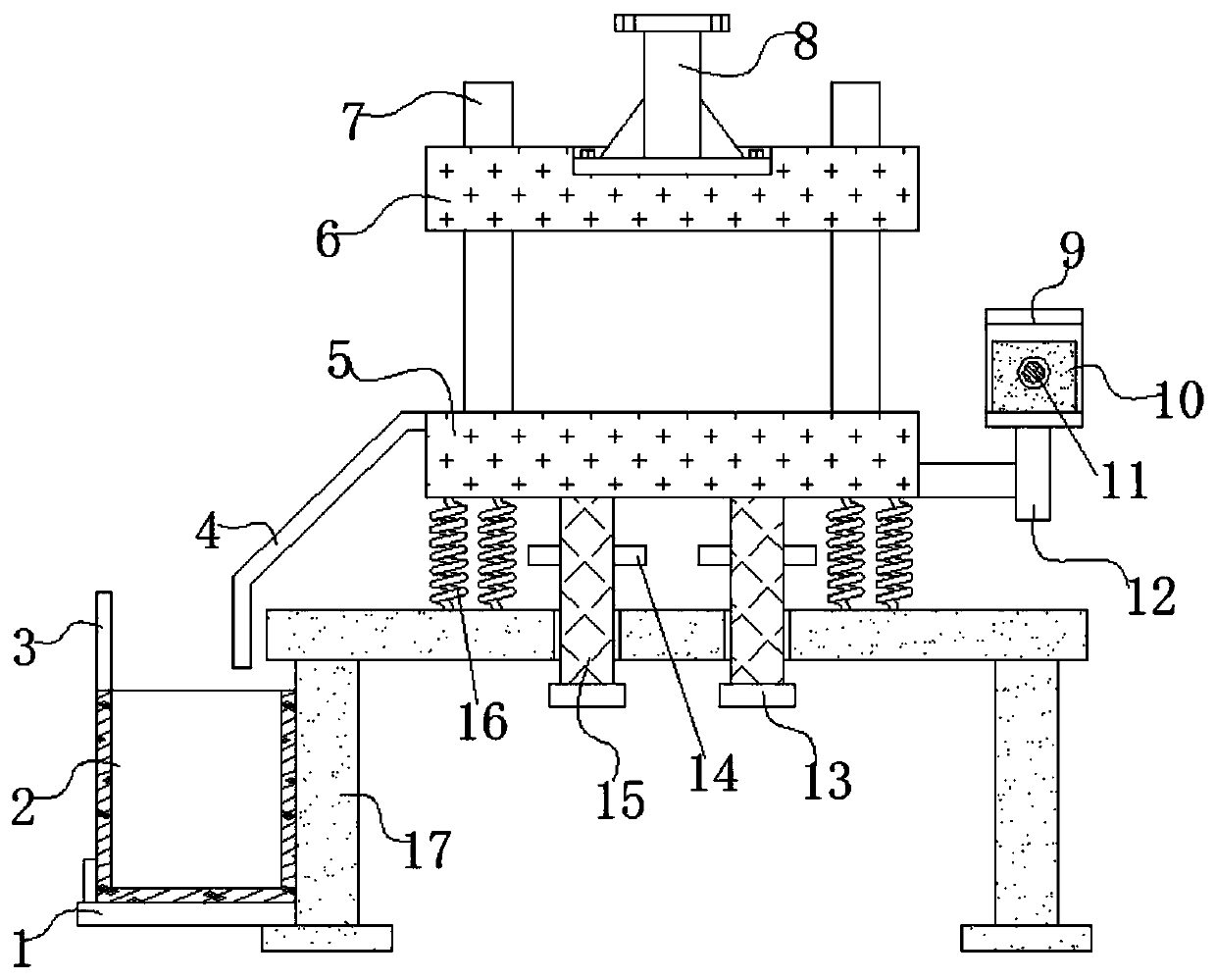
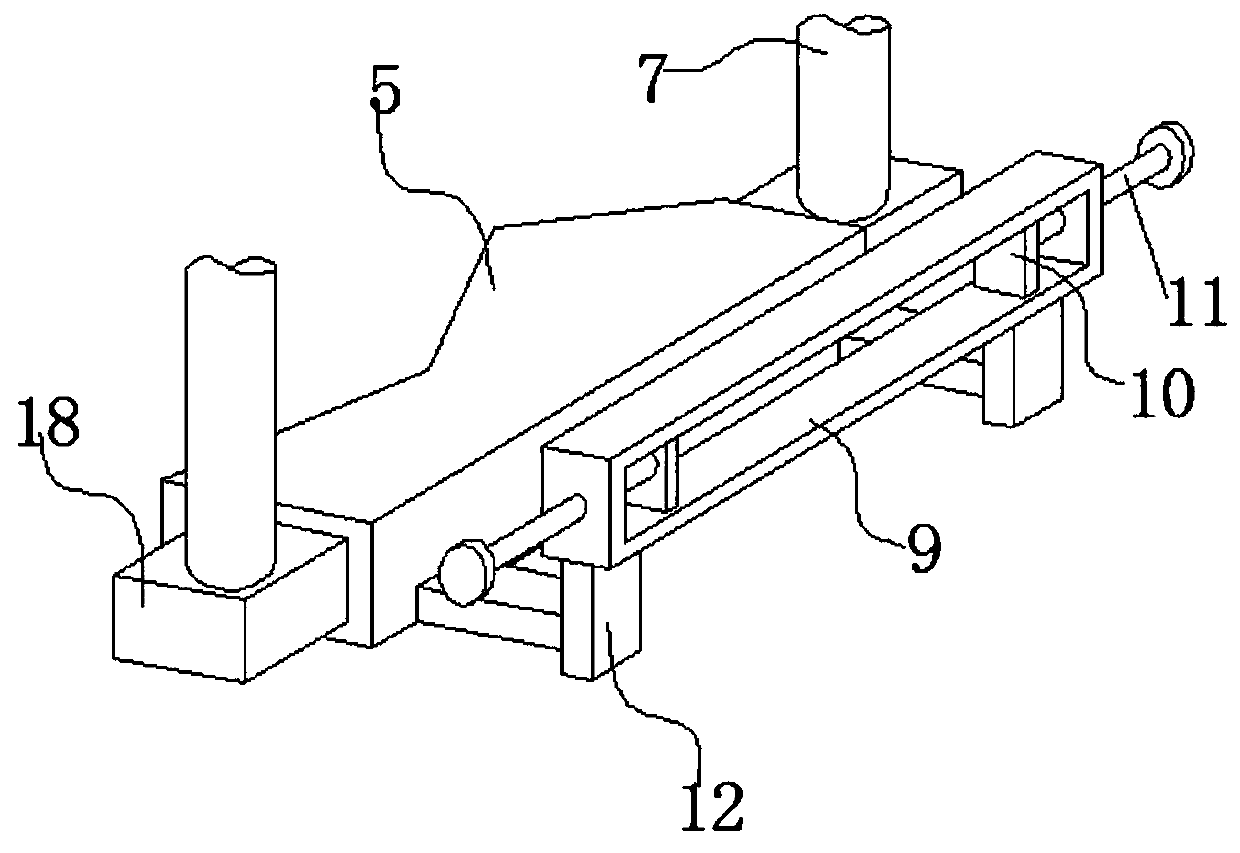
[0022] refer to figure 1 and figure 2 , a stamping device for processing automobile body parts, comprising a fixed mold base 5, a movable mold base 6 and a workbench 17, the top of the workbench 17 is welded with multiple sets of springs 16, and the top of the springs 16 is welded to the bottom of the fixed mold base 5 , the top of workbench 17 is provided with a plurality of through holes, and column 15 is inserted in the through holes, and the top of column 15 is welded with the bottom of fixed mold base 5, and the outer wall of column 15 is welded with limit plate 14, limit plate 14 is located above the workbench 17, the bottom of the column 15 is welded with a backing plate 13, the outer wall of one side of the fixed mold seat 5 is welded with two cross bars, and one end of the two cross bars is welded with a telescopic rod 12, further The telescopic rod 12 is a manual lockable telescopic rod. The telescopic rod 12 is convenient for the staff to adjust the height of the ...

Embodiment 2

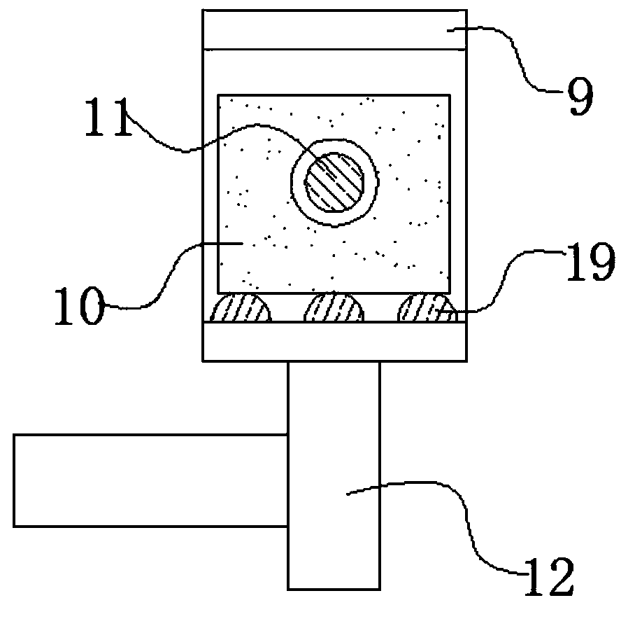
[0029] refer to image 3 , a stamping device for processing automobile body parts. Compared with Embodiment 1, the main difference of this embodiment is that in this embodiment, the bottom inner wall of the rectangular frame 9 is welded with a plurality of horizontal bars 19, and the end faces of the horizontal bars 19 are half Round, the bottom of the side block 10 is in contact with the top of the bar 19 .

[0030] Working principle: when in use, the bottom of the plate is located on the horizontal bar 19, because the end face of the horizontal bar 19 is semicircular, so the contact area between it and the plate is small, which reduces the friction force when the plate moves.


PUM


Abstract

The invention discloses a stamping device for automotive body accessory processing. The device comprises a stationary die holder, a movable die holder and a worktable; the top of the worktable is fixedly connected with a plurality of groups of springs; the top ends of the springs are fixedly connected with the bottom of the stationary die holder; a plurality of through holes are formed in the topof the worktable; stand columns are inserted in the through holes; the top ends of the stand columns are fixedly connected with the bottom of the stationary die holder; the outer walls of the stand columns are fixedly connected with limiting plates; the limiting plates are located above the worktable; the bottom ends of the stand columns are fixedly connected with base plates; the outer wall, on one side, of the stationary die holder is fixedly connected with two cross bars; and one end of each cross bar is fixedly connected with a telescopic rod. The stamping device for automotive body accessory processing provided by the invention is convenient for the workers to horizontally place the bar-shaped plates, so as to decrease the operation errors and improve the practicability of the device.

Description

technical field [0001] The invention relates to the technical field of stamping devices, in particular to a stamping device for processing automobile body parts. Background technique [0002] In the production process of automobile body reinforced plate girder, most of its accessories are produced by stamping device. When stamping, the strip-shaped plate is inserted between the movable mold and the fixed mold. As the fixed mold moves down reciprocatingly, the plate The workpiece is stamped out, and the staff moves the strip plate toward the side close to the movable mold as the fixed mold moves down reciprocatingly, and pushes out the stamped material, and provides the plate for the next stamping raw material. [0003] At present, most of the existing stamping devices for the processing of automobile body parts on the market have the following deficiencies: when stamping, the staff manually pushes the plate forward, which may make the plate tilt, which in turn leads to erro...

Claims


Application Information

Patent Timeline
Patent Type & Authority Applications(China)
IPC IPC(8): B21D22/02B21D43/20B21D43/00F16F15/04
CPCB21D22/02B21D43/003B21D43/20F16F15/04
Inventor 张一张永刚王正金
Owner 十堰市寅云实业有限公司
Why Eureka
Try Eureka