Variable-diameter mold pipeline device facilitating pouring and stripping and variable-diameter method

A mold pipe and mold release technology, applied in the direction of manufacturing tools, reinforcement molding, ceramic molding machines, etc., can solve the problems of affecting the smoothness of the inner wall of the cement pipe, inconvenient disassembly of the inner mold, and scratching of the cement pipe, etc. Efficiency and quality of installation and disassembly, convenient and quick installation and disassembly, and the effect of improving quality

Active Publication Date: 2019-10-25
芜湖新芜新型建材有限公司
View PDF14 Cites 2 Cited by
  • Summary
  • Abstract
  • Description
  • Claims
  • Application Information

AI Technical Summary

Problems solved by technology

[0003] However, after the cement pipe is formed by vibrating the mold, the inner mold and the cement pipe are firmly in contact, which makes it inconvenient to disassemble the inner mold, and even causes scratches inside the cement pipe. When it is used for drainage, it is easy to cause scraps to be scratched Areas are piled up, and at the same time, rubber hammers are often used to knock the outer mold of the mold. The work efficiency is low during the knocking process, and the vibration effect of the inner mold is poor, which in turn affects the smoothness of the inner wall of the cement pipe, and the outer mold is mostly fixed by bolts. The installation and disassembly are not convenient and fast enough, and the installation is easy to cause damage to the bolts, which is not convenient for uniform force on the side wall of the outer mold cavity. At the same time, during the process of adding concrete, due to the single addition direction, the concrete fills the entire mold under the action of gravity, which is easy to cause concrete distribution. Unevenness, which in turn affects the compressive performance of the cement pipe

Method used


Image

  • Variable-diameter mold pipeline device facilitating pouring and stripping and variable-diameter method
  • Variable-diameter mold pipeline device facilitating pouring and stripping and variable-diameter method
  • Variable-diameter mold pipeline device facilitating pouring and stripping and variable-diameter method

Examples


Embodiment Construction

[0028] In order to make the technical means, creative features, goals and effects achieved by the present invention easy to understand, the present invention will be further described below in conjunction with specific embodiments.

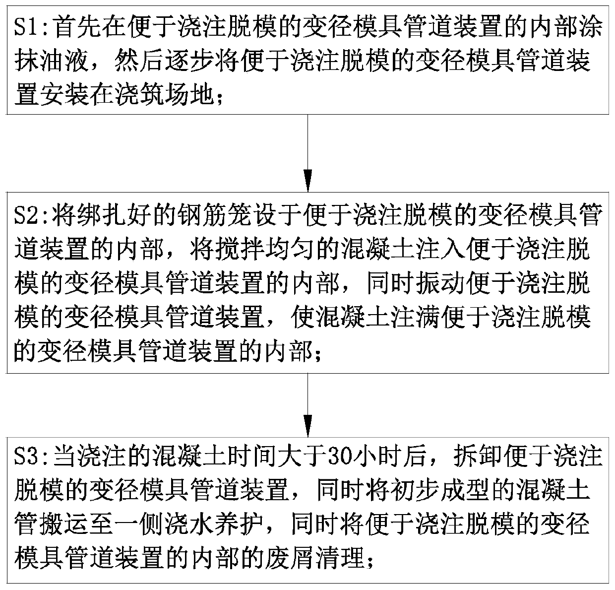
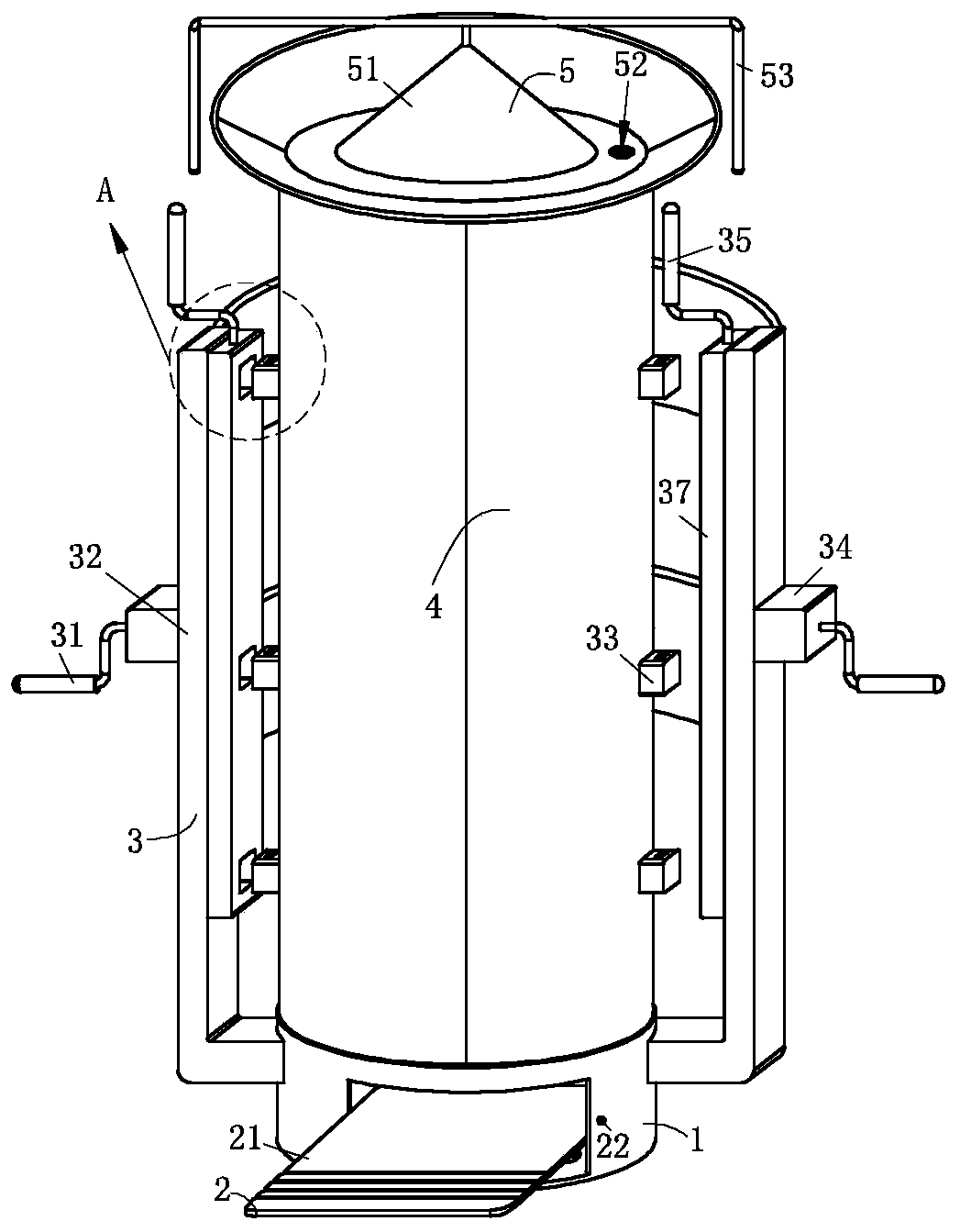
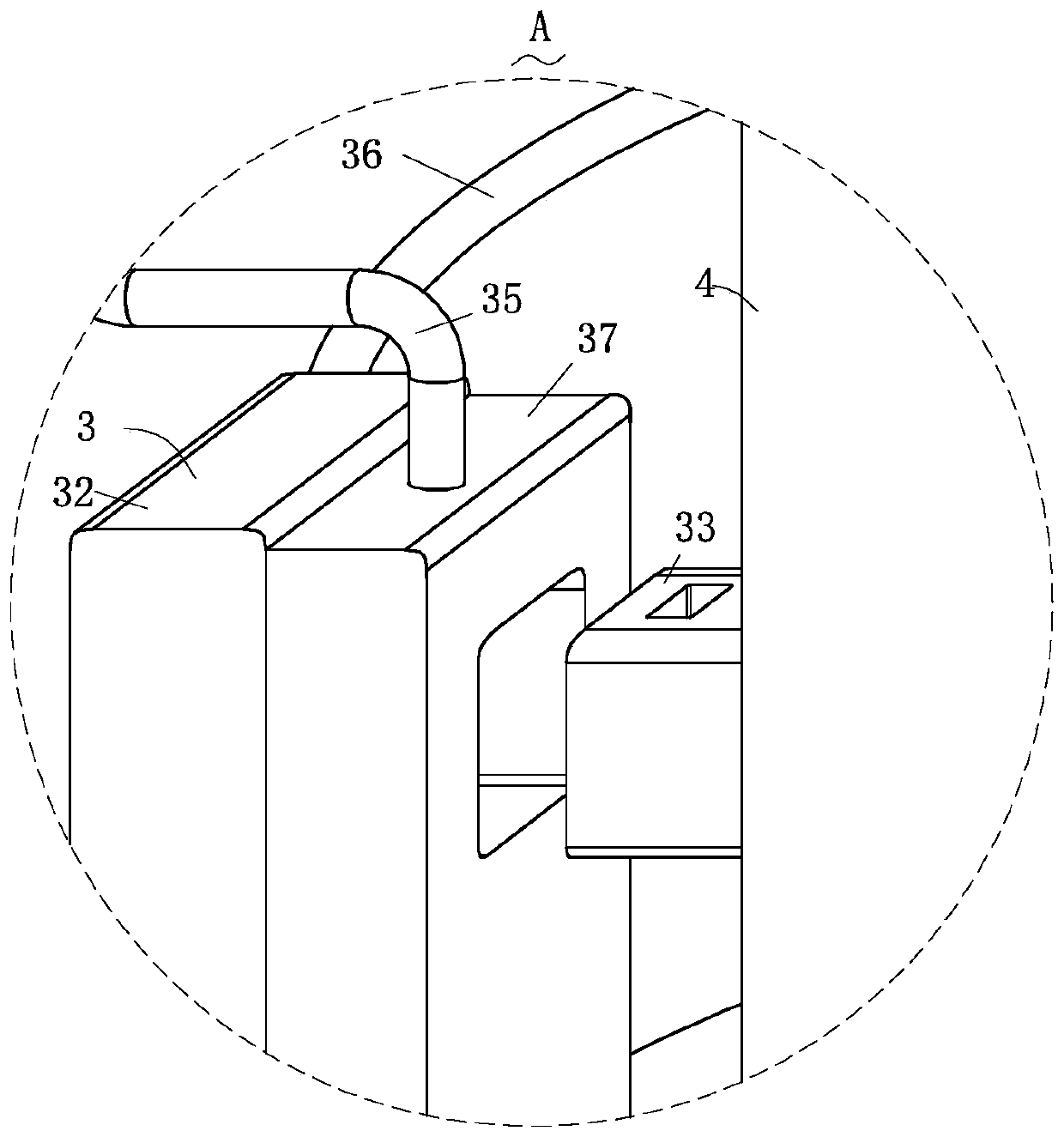
[0029] Such as Figure 1-Figure 7 As shown, a kind of variable diameter mold pipeline device and the variable diameter method that are convenient for pouring demoulding according to the present invention, the method steps are as follows:

[0030] S1: firstly, oil liquid is applied to the inside of the variable-diameter mold pipeline device that is convenient for pouring and demoulding, and then the variable-diameter mold pipeline device that is convenient for pouring and demoulding is gradually installed on the pouring site;

[0031] S2: Set the bundled reinforcement cage inside the variable-diameter mold pipeline device that is convenient for pouring and demoulding, inject evenly mixed concrete into the interior of the variable-diameter mold pipe...


PUM


Abstract

The invention relates to the field of molds, in particular to a variable-diameter mold pipeline device facilitating pouring and stripping and a variable-diameter method. The variable-diameter mold pipeline device convenient facilitating pouring and stripping in the method comprises a base, a vibrating structure, a limiting structure, first mold plates, a flow guide structure and a mold stripping structure, wherein the limiting structure is connected to the base, so that the two first mold plates which are of semi-annular structures and are used for pouring a concrete pipe can be convenientlycontrolled to move north or relative to each other through the limiting structure, so that the stress between the two first mold plates is more uniform, repositioning in the process of the first moldplates is avoided, the mold stripping structure is arranged inside a cylinder cavity defined by the two first mold plates, the mold stripping structure is fixed on the base, so that the stress of an inner mold is more uniform, mold stripping after the concrete pipe is formed is more convenient and rapid, the concrete pipe is effectively prevented from rotating in the mold stripping process, so that the mold stripping efficiency and quality of the concrete pipe is greatly improved.

Description

technical field [0001] The invention relates to the field of moulds, in particular to a diameter-changing mold pipeline device and a diameter-changing method that are convenient for pouring and demolding. Background technique [0002] Cement pipes are also called cement pressure pipes and reinforced concrete pipes. They can be used as sewer pipes in urban construction, sewage, flood control and drainage, as well as water pipes and farmland wells used in some special factories and mines. They are generally divided into: flat reinforced concrete Cement pipes, flexible tongue and groove reinforced concrete pipes, socket reinforced concrete pipes, F-shaped steel socket cement pipes, flat ring joint cement pipes, and tongue and groove cement pipes are mostly manufactured by mold vibration extrusion in remote rural areas. The process adopts semi-dry hard concrete, and the vertical cloth inner mold is vibrated and radially extruded. During molding, the vibration force and amplitude...

Claims


Application Information

Patent Timeline
Patent Type & Authority Applications(China)
IPC IPC(8): B28B21/14B28B21/56B28B21/90
CPCB28B21/14B28B21/56B28B21/90
Inventor 不公告发明人
Owner 芜湖新芜新型建材有限公司
Why Eureka
Try Eureka